NSI50010YT1G ON Semiconductor, NSI50010YT1G Datasheet

IC REG CCR 50V 10MA SOD123-2

NSI50010YT1G

Manufacturer Part Number
NSI50010YT1G
Description
IC REG CCR 50V 10MA SOD123-2
Manufacturer
ON Semiconductor
Type
Linear (Non-Switching)r
Datasheet

Specifications of NSI50010YT1G

Package / Case
SOD-123
Operating Temperature
-55°C ~ 150°C
Number Of Outputs
1
Current - Output / Channel
10mA
Internal Switch(s)
No
Operating Supply Voltage
50 V
Maximum Supply Current
13 mA
Maximum Power Dissipation
460 mW
Maximum Operating Temperature
+ 125 C
Mounting Style
SMD/SMT
Minimum Operating Temperature
- 55 C
Lead Free Status / RoHS Status
Lead free / RoHS Compliant
Voltage - Supply
-
Voltage - Output
-
Frequency
-
Efficiency
-
Topology
-
Lead Free Status / Rohs Status
Lead free / RoHS Compliant

Available stocks

Company
Part Number
Manufacturer
Quantity
Price
Part Number:
NSI50010YT1G
Manufacturer:
ON
Quantity:
3 000
Part Number:
NSI50010YT1G
0
NSI50010YT1G
Constant Current Regulator
& LED Driver
50 V, 10 mA + 30%, 460 mW Package
and robust device designed to provide a cost−effective solution for
regulating current in LEDs. The CCR is based on patent-pending
Self-Biased Transistor (SBT) technology and regulates current over a
wide voltage range. It is designed with a negative temperature
coefficient to protect LEDs from thermal runaway at extreme voltages
and currents.
only 0.5 V Vak. It requires no external components allowing it to be
designed as a high or low−side regulator. The high anode-cathode
voltage rating withstands surges common in Automotive, Industrial
and Commercial Signage applications. The CCR comes in thermally
robust packages and is qualified to AEC-Q101 standard.
Features
Applications
Stresses exceeding Maximum Ratings may damage the device. Maximum
Ratings are stress ratings only. Functional operation above the Recommended
Operating Conditions is not implied. Extended exposure to stresses above the
Recommended Operating Conditions may affect device reliability.
MAXIMUM RATINGS
© Semiconductor Components Industries, LLC, 2009
December, 2009 − Rev. 0
Anode−Cathode Voltage
Reverse Voltage
Operating and Storage Junction
ESD Rating:
The linear constant current regulator (CCR) is a simple, economical
The CCR turns on immediately and is at 40% of regulation with
Compliant
Instrument Backlighting, CHMSL, Map Light
Lettering
Robust Power Package: 460 mW
Wide Operating Voltage Range
Immediate Turn-On
Voltage Surge Suppressing − Protecting LEDs
AEC-Q101 Qualified
SBT (Self−Biased Transistor) Technology
Negative Temperature Coefficient
These Devices are Pb−Free, Halogen Free/BFR Free and are RoHS
Automobile: Chevron Side Mirror Markers, Cluster, Display &
AC Lighting Panels, Display Signage, Decorative Lighting, Channel
Switch Contact Wetting
Application Note AND8391/D − Power Dissipation Considerations
Application Note AND8349/D − Automotive CHMSL
Temperature Range
Rating
Human Body Model
Machine Model
(T
A
= 25°C unless otherwise noted)
Vak Max
Symbol
T
ESD
J
V
, T
R
stg
−55 to +150
Value
500
50
Class 1C
Class B
1
Unit
mV
°C
V
NSI50010YT1G
†For information on tape and reel specifications,
including part orientation and tape sizes, please
refer to our Tape and Reel Packaging Specifications
Brochure, BRD8011/D.
Device
(Note: Microdot may be in either location)
ORDERING INFORMATION
AJ
M
G
MARKING DIAGRAM
1
http://onsemi.com
I
reg(SS)
1
@ Vak = 7.5 V
SOD−123
(Pb−Free)
Cathode 1
Package
CASE 425
SOD−123
Anode 2
STYLE 1
= Device Code
= Date Code
= Pb−Free Package
AJ M G
= 10 mA
Publication Order Number:
G
3000/Tape & Reel
2
2
Shipping
NSI50010Y/D

Related parts for NSI50010YT1G

NSI50010YT1G Summary of contents

Page 1

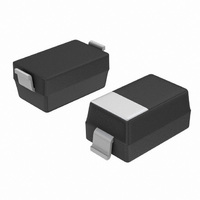
... Pb−Free Package (Note: Microdot may be in either location) ORDERING INFORMATION Device Package Shipping NSI50010YT1G SOD−123 3000/Tape & Reel (Pb−Free) †For information on tape and reel specifications, including part orientation and tape sizes, please refer to our Tape and Reel Packaging Specifications Brochure, BRD8011/D ...

Page 2

ELECTRICAL CHARACTERISTICS Characteristic Steady State Current @ Vak = 7.5 V (Note 1) Voltage Overhead (Note 2) Pulse Current @ Vak = 7.5 V (Note 3) Capacitance @ Vak = 7.5 V (Note 4) Capacitance @ Vak = 0 V ...

Page 3

Minimum FR−4 @ 300 −10 −20 − Vak, ANODE−CATHODE VOLTAGE (V) Figure 1. General Performance Curve for CCR Non−Repetitive Pulse Test ...

Page 4

APPLICATIONS Anode Cathode LED LED + V in − HF3−R5570 HF3−R5570 LED LED HF3−R5570 HF3−R5570 LED LED HF3−R5570 HF3−R5570 Figure 7. Typical Application Circuit (10 mA each LED String) Number of LED’s that can be connected is ...

Page 5

... Comparison of LED Circuit using CCR vs. Resistor Biasing ON Semiconductor CCR Design Constant brightness over full Automotive Supply Voltage (more efficient), see Figure 9 Little variation of power in LEDs, see Figure 10 Constant current extends LED strings lifetime, see Figure 9 Current decreases as voltage increases, see Figure 9 ...

Page 6

... *For additional information on our Pb−Free strategy and soldering details, please download the ON Semiconductor Soldering and Mounting Techniques Reference Manual, SOLDERRM/D. ON Semiconductor and are registered trademarks of Semiconductor Components Industries, LLC (SCILLC). SCILLC reserves the right to make changes without further notice to any products herein. SCILLC makes no warranty, representation or guarantee regarding the suitability of its products for any particular purpose, nor does SCILLC assume any liability arising out of the application or use of any product or circuit, and specifically disclaims any and all liability, including without limitation special, consequential or incidental damages. “ ...

Related keywords