ISL78100ARZ Intersil, ISL78100ARZ Datasheet - Page 15

ISL78100ARZ
Manufacturer Part Number
ISL78100ARZ
Description
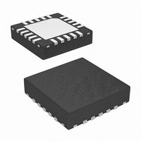
IC LED DRIVER AUTOMOTIVE 20-QFN
Manufacturer
Intersil
Type
Automotiver
Datasheet
1.ISL78100ARZ.pdf
(19 pages)
Specifications of ISL78100ARZ
Topology
PWM, Step-Down (Buck), Step-Up (Boost), Switched Capacitor (Charge Pump)
Number Of Outputs
1
Internal Driver
Yes
Type - Primary
Automotive, Backlight
Frequency
800kHz ~ 1.2MHz
Voltage - Supply
2.7 V ~ 16 V
Voltage - Output
32V
Mounting Type
Surface Mount
Package / Case
20-VQFN Exposed Pad, 20-HVQFN, 20-SQFN, 20-DHVQFN
Operating Temperature
-40°C ~ 105°C
Current - Output / Channel
1A
Internal Switch(s)
Yes
Efficiency
90%
Lead Free Status / RoHS Status
Lead free / RoHS Compliant
CERAMIC CAPACITORS
Many ceramic capacitors have strong voltage and
temperature coefficients, which reduces effective
capacitance as the applied voltage or operating temperature
is increased. Pay careful attention when selecting ceramic
capacitor type. X5R and X7R families provide much better
stability than Y5V, which should generally be avoided unless
additional capacitance is added to compensate for the
significant changes in value, which occurs overvoltage and
temperature.
Layout Considerations
PCB layout is very important for the converter to function
properly. The following general guidelines should be
followed:
• Separate the Power Ground and Signal Ground; connect
• Maximize the Power Ground area as much as possible. It
• Place the input capacitor close to VIN and SWS1, SWS2
• Make the following PC traces as short as possible:
• Feedback signals levels are small to improve efficiency.
them only at one point close to the GND pin.
is essential to ensure the Power Ground return between
C
pins in boost mode.
- from SWD1, SWD2 to the inductor in boost mode
- from SWS1,SWS2 to the inductor in buck mode
- from C
Ensure the reference connection (GND or VIN) between
the sense resistor and IC pin doesn't carry switching
current.
CAPACITOR TYPE
IN
100mV
200mV
200mV
, C
50mV
X7R, 10V
X5R, 25V
Y5V, 6.3V
VFB
TABLE 5. CERAMIC CAPACITOR VARIABILITY
OUT
OUT
, and SWS1,2 as least obstructive as possible.
to PGND
100mA
350mA
TYPICAL VOLTAGE
50mA
I
OUT
1A
-90% at 6.3V
-30% at 10V
-50% at 25V
VARIATION
15
Electrolytic
Electrolytic
Electrolytic
Electrolytic
TABLE 4. BOOST MODE COMPENSATION 12V OPERATION
VOUT (V)
Ceramic
Ceramic
Ceramic
Ceramic
LED’s
TEMPERATURE
-15% at +125°C
-65% at +85°C
-9% at +85°C
VARIATION
DMIN
DMIN
DMIN
DMIN
7
2
ISL78100
DMIN
DMIN
DMIN
DMIN
10.5
3
• Place several via holes (thermal vias) under the chip to a
• Maximize the copper area around the thermal vias to
Cost-Sensitive Applications
For cost-sensitive applications, the BOM can be reduced
considerably by:
In this configuration, light level may be controlled using the
EN/PWM input to modulate the output current.
In the absence of the load isolation switch, LED bias current
will vary with PWM duty cycle, due to the discharge of the
output capacitor by the LED’s during the PWM off-time.
Therefore, low dimming frequencies can only be used in
such an application.
1. Removing temperature compensation
2. Removing the fault-protection switch
3. Removing the load isolation switch
4. Switching the FB into internal fixed bias mode (400mV
backside ground plane to improve heat dissipation
spread heat away from the chip.
across V
DMIN
DMIN
DMIN
DMIN
14
4
FB
)
60µF
47µF
40µF
47µF
40µF
47µF
20µF
17.5
5
40µF
47µF
20µF
47µF
20µF
47µF
20µF
21
6
40µF
40µF
40µF
40µF
24.5
7
December 17, 2007
40µF
40µF
40µF
40µF
28
FN6626.0
8


