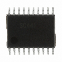
SC441TETRT Semtech, SC441TETRT Datasheet - Page 14

SC441TETRT
Manufacturer Part Number
SC441TETRT
Description
IC LED DRIVR WHT BCKLGT 20-TSSOP
Manufacturer
Semtech
Type
Backlight, White LEDr
Datasheet
1.SC441TETRT.pdf
(19 pages)
Specifications of SC441TETRT
Constant Current
Yes
Topology
PWM, Step-Up (Boost)
Number Of Outputs
4
Internal Driver
Yes
Type - Primary
Backlight
Frequency
560kHz ~ 840kHz
Voltage - Supply
4.5 V ~ 21 V
Voltage - Output
36V
Mounting Type
Surface Mount
Package / Case
20-TSSOP
Current - Output / Channel
150mA
Internal Switch(s)
Yes
Efficiency
90%
Lead Free Status / RoHS Status
Lead free / RoHS Compliant
Operating Temperature
-
Other names
SC441TETR
D
C
B
A
Applications Information (continued)
D_max, the designer should be aware of possible parasitic
elements from PWM dimming interface to the PWM pin of
SC441. Usually, simply checking signal D_max at PWM pin
of SC441 is sufficient.
Linear Dimming
The linear dimming control is available for SC441 by
applying an external control voltage on IOSET pin
through an external resistor-like circuit (shown below).
External environment brightness compensation can also
be achieved when the control voltage is generated by a
light sensor circuit.
The IOSET voltage is 0.5V when linear dimming is used and
the minimum IOSET current must be higher than 27µA
(i.e. 15mA per LED string). The external control voltage
slew rate must slow at 1V/10ms.
LED Strings Connection
Generally, LED strings are connected to IO1 ~ IO4 pins
through a mechanical connector which, generally, can-
not support an electrical connection thereby resulting in
significant noise. Consequently, the SC441 LED short-cir-
cuit protection may false trip when the noise level is large.
Certain ceramic decoupling capacitor on pins IO1 ~ IO4
to GND are useful to prevent the SC441 from noise influ-
ence.
As a general guideline, the decoupling capacitance should
be limited as follows.
Where, I_LED is the LED current per string, Vo is the Boost
output voltage and C_dcple is the suggested decoupling
capacitor value.
For example, if I_LED=10mA, Vo=13.5V, the calculated
upper bound of C_dcple is about 444pF. One could use
390pF or less in the circuit. If I_LED=100mA, Vo=13.5V,
the calculated upper bound of C_dcple is about 4.44nF.
One may use 3.9nF or less in the circuit. In some applica-
tions, circuit designers tend to select the decoupling ca-
pacitors in the range of (100pF ~ 1nF).
© 2010 Semtech Corporation
5
5
V_EXT
4
4
C
dcple
R_EXT
NOT RECOMMENDED FOR NEW DESIGNS: SEE SC441A
<
I
LED
*
0
3
3
6 .
V
uS
o
R_IOSET
2
2
IOSET
1
1
D
C
B
A
For some low LED current (e.g. 10mA) applications, it is
recommended to add 1M-10Mohm resistor from IO pin
to GND in order to reduce IO pin voltage during PWM
dimming.
Parallel Operation
When two or more SC441s are operating in parallel for a
large-sized panel application, audible noise may be ob-
served due to non-synchronous switching frequency. The
ripple voltage on the input voltage rail will be modulat-
ed by the beat frequency resulting in audible noise. This
situation can be resolved by adding an input inductor
between input voltage rail and the SC441 VIN pin. This
situation can also be improved by adding more input de-
coupling capacitors.
Inductor Selection
The inductance value of the inductor affects the convert-
er’s steady state operation, transient response, and its
loop stability. Special attention needs to be paid to three
specifications of the inductor, its value, its DC resistance
and saturation current. The inductor’s inductance value
also determines the inductor ripple current. The converter
can operate in either CCM or DCM depending on its work-
ing conditions. The inductor DC current or input current
can be calculated as,
I
Then the duty ratio is,
V
diode
When the boost converter runs in DCM ( L < L
the advantages of small inductance and quick transient
response while avoiding the bandwidth limiting instability
of the RHP zero found in CCM boost converters.
IN
D
- Input current;
– Forward conduction drop of the output rectifying
V
V
I
η – Efficiency of the boost converter.
OUT
OUT
IN
– Input voltage;
– Output current;
– Boost output voltage;
www.semtech.com
boundary
SC441
), it takes
14


