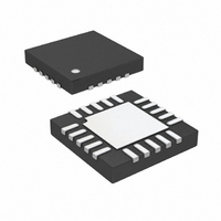
LT3477EUF#TRPBF Linear Technology, LT3477EUF#TRPBF Datasheet - Page 6

LT3477EUF#TRPBF
Manufacturer Part Number
LT3477EUF#TRPBF
Description
IC LED DRVR HP CONST CURR 20-QFN
Manufacturer
Linear Technology
Type
High Power, Constant Currentr
Datasheet
1.LT3477EUFPBF.pdf
(20 pages)
Specifications of LT3477EUF#TRPBF
Constant Current
Yes
Constant Voltage
Yes
Topology
Flyback, PWM, SEPIC, Step-Down (Buck), Step-Up (Boost)
Number Of Outputs
1
Internal Driver
Yes
Type - Primary
General Purpose
Type - Secondary
White LED
Frequency
200kHz ~ 3.5MHz
Voltage - Supply
2.5 V ~ 25 V
Mounting Type
Surface Mount
Package / Case
20-QFN
Operating Temperature
-40°C ~ 85°C
Current - Output / Channel
3A
Internal Switch(s)
Yes
Efficiency
93%
Lead Free Status / RoHS Status
Lead free / RoHS Compliant
Voltage - Output
-
Available stocks
Company
Part Number
Manufacturer
Quantity
Price
PIN FUNCTIONS
I
noninverting input to the second current sense amplifi er.
Connect to I
I
inverting input to the second current sense amplifi er.
Connect to I
I
noninverting input to the fi rst current sense amplifi er.
Connect to I
I
verting input to the fi rst current sense amplifi er. Connect
to I
LT3477
BLOCK DIAGRAM
6
SP2
SN2
SP1
SN1
SP1
(Pin 13/Pin 11): Second Current Sense (+) Pin. The
(Pin 14/Pin 12): Second Current Sense (–) Pin. The
(Pin 16/Pin 14): First Current Sense (–) Pin. The in-
(Pin 15/Pin 13): First Current Sense (+) Pin. The
if not used.
I
I
I
I
I
I
FBP
FBN
V
SP1
SN1
ADJ1
SP2
SN2
ADJ2
REF
SN2
SP2
SN1
–
–
–
+
+
+
if not used.
if not used.
if not used.
IA1
IA2
VA
1.25V
V
REF
V
V
ADJ
ADJ
(QFN/TSSOP)
–
–
+
+
+
+
SHDN
A1
A2
V
IN
Figure 1. LT3477 Block Diagram
A3
SS
SLOPE
GND (Pins 17/Pin 15): Ground. Tie directly to local
ground plane.
SW (Pins 18, 19/Pins 16, 17): Switch Pins. Collector of
the internal NPN power switch. Connect the inductor and
diode here and minimize the metal trace area connected
to this pin to minimize electromagnetic interference.
Exposed Pad (Pin 21/Pin 21): Power Ground. Must be
soldered to PCB ground for electrical contact and rated
thermal performance.
∑
V
C
–
+
A4
OSCILLATOR
R
S
R
T
Q
+
–
Q1
SW
3477 F01
3477fc


