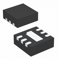
LT3491EDC#TRPBF Linear Technology, LT3491EDC#TRPBF Datasheet - Page 10

LT3491EDC#TRPBF
Manufacturer Part Number
LT3491EDC#TRPBF
Description
IC LED DRIVER WHITE BCKLGT 6-DFN
Manufacturer
Linear Technology
Type
Backlight, White LEDr
Datasheet
1.LT3491EDCTRMPBF.pdf
(16 pages)
Specifications of LT3491EDC#TRPBF
Topology
PWM, Step-Up (Boost)
Number Of Outputs
1
Internal Driver
Yes
Type - Primary
Backlight
Type - Secondary
White LED
Frequency
2.3MHz
Voltage - Supply
2.5 V ~ 12 V
Mounting Type
Surface Mount
Package / Case
6-DFN
Operating Temperature
-40°C ~ 85°C
Current - Output / Channel
200mA
Internal Switch(s)
Yes
Lead Free Status / RoHS Status
Lead free / RoHS Compliant
Voltage - Output
-
Efficiency
-
Available stocks
Company
Part Number
Manufacturer
Quantity
Price
APPLICATIO S I FOR ATIO
LT3491
The time it takes for the LED current to reach its pro-
grammed value sets the achievable dimming range for a
given PWM frequency. For example, the settling time of
the LED current in Figure 7 is approximately 30µs for a 3V
input voltage. The achievable dimming range for this
application and 100Hz PWM frequency can be determined
using the following method.
Example:
The calculations show that for a 100Hz signal the dimming
range is 300 to 1. In addition, the minimum PWM duty
cycle of 0.3% ensures that the LED current has enough
time to settle to its final value. Figure 8 shows the dimming
range achievable for three different frequencies with a
settling time of 30µs.
The dimming range can be further extended by changing
the amplitude of the PWM signal. The height of the PWM
signal sets the commanded sense voltage across the
sense resistor through the CTRL pin. In this manner both
analog dimming and direct PWM dimming extend the
dimming range for a given application. The color of the
LEDs no longer remains constant because the forward
current of the LED changes with the height of the CTRL
signal. For the four LED application described above, the
LEDs can be dimmed first, modulating the duty cycle of the
PWM signal. Once the minimum duty cycle is reached, the
height of the PWM signal can be decreased below 1.5V
10
D
Min
Duty Cycle Range
ƒ
t
PERIOD
i i m Range
=
100
Duty Cycle
Hz t
=
,
ƒ
1
=
=
SETTLE
t
t
100
PERIOD
SETTLE
1
=
U
t
t
=
=
PERIOD
SETTLE
=
100
0 01
30
=
.
U
0 01
µs
30
%
s
.
•
→
µs
100
s
0 3
=
. %
W
=
300 1
0 01
30
.
at
:
µs
s
100
•
10 0 0 0 3
Hz
U
=
. %
down to 100mV. The use of both techniques together
allows the average LED current for the four LED applica-
tion to be varied from 20mA down to less than 20µA.
Figure 9 shows the application for dimming using both
analog dimming and PWM dimming. A potentiometer
must be added to ensure that the gate of the NMOS
receives a logic-level signal, while the CTRL signal can be
adjusted to lower amplitudes.
3V TO 5V
V
Figure 9. Li-Ion to Four White LEDs with Both
PWM Dimming and Analog Dimming
IN
1
Figure 8. Dimming Range Comparison
of Three PWM Frequencies
10µH
C1
1µF
L1
10kHz
PWM DIMMING RANGE
10
SW
GND
CTRL
LT3491
V
1kHz
IN
2.5V
0V
100
CAP
LED
PWM
FREQ
100k
100Hz
3491 F08
1000
Q1
Si2302
R
10Ω
SENSE
3491 F09
C2
1µF
3491fa


