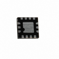
MIC2846A-PGYMT TR Micrel Inc, MIC2846A-PGYMT TR Datasheet - Page 16

MIC2846A-PGYMT TR
Manufacturer Part Number
MIC2846A-PGYMT TR
Description
IC LED DRIVR WHITE BCKLGT 14TMLF
Manufacturer
Micrel Inc
Series
Dynamic Average Matching™r
Type
Backlight, White LEDr
Datasheet
1.MIC2846A-PPYMT_TR.pdf
(19 pages)
Specifications of MIC2846A-PGYMT TR
Topology
Linear (LDO)
Number Of Outputs
6
Internal Driver
Yes
Type - Primary
Backlight, Flash/Torch
Type - Secondary
White LED
Voltage - Supply
3 V ~ 5.5 V
Mounting Type
Surface Mount
Package / Case
14-TMLF®, QFN
Operating Temperature
-40°C ~ 125°C
Current - Output / Channel
20mA
Internal Switch(s)
Yes
Lead Free Status / RoHS Status
Lead free / RoHS Compliant
Voltage - Output
-
Frequency
-
Efficiency
-
Other names
576-3479-2
LDO
MIC2846A LDOs are low noise 150mA LDOs. The
MIC2846A LDO regulator is fully protected from damage
due to fault conditions, offering linear current limiting and
thermal shutdown.
Input Capacitor
The MIC2846A stability can be maintained using a
ceramic input capacitor of 1µF. Low-ESR ceramic
capacitors provide optimal performance at a minimum
amount of space. Additional high-frequency capacitors,
such as small-valued NPO dielectric-type capacitors,
help filter out high-frequency noise and are good
practice in any noise sensitive circuit. X5R or X7R
dielectrics are recommended for the input capacitor. Y5V
dielectrics
temperature and are therefore, not recommended.
Output Capacitor
The MIC2846A LDOs require an output capacitor of at
least 1µF or greater to maintain stability, however, the
output capacitor can be increased to 2.2µF to reduce
output noise without increasing package size. The
design is optimized for use with low-ESR ceramic chip
capacitors. High ESR capacitors are not recommended
because they may cause high frequency oscillation.
X7R/X5R
recommended due to their improved temperature
performance compared to Z5U and Y5V capacitors.
X7R-type capacitors change capacitance by 15% over
their operating temperature range and are the most
stable type of ceramic capacitors. Z5U and Y5V
dielectric capacitors change value by as much as 50%
and 60%, respectively, over their operating temperature
ranges. To use a ceramic chip capacitor with Y5V
dielectric, the value must be much higher than an X7R
ceramic capacitor to ensure the same minimum
capacitance over the equivalent operating temperature
range.
No-Load Stability
Unlike many other voltage regulators, the MIC2846A
LDOs will remain stable and in regulation with no load.
Thermal Considerations
The MIC2846A LDOs are each designed to provide
150mA of continuous current. Maximum ambient
operating temperature can be calculated based on the
Micrel Inc.
April 2010
dielectric-type
lose
most
of
ceramic
their
capacitance
capacitors
over
are
16
output current and the voltage drop across the part. For
example if the input voltage is 3.6V, the output voltage is
2.8V, and the output current = 150mA. The actual power
dissipation of the regulator circuit can be determined
using the equation:
Because this device is CMOS and the ground current
(I
dissipation contributed by the ground current is < 1% and
can be ignored for this calculation.
Since there are two LDOs in the same package, the
power dissipation must be calculated individually and
then summed together to arrive at the total power
dissipation.
To
temperature of the package, use the junction-to-ambient
thermal resistance (θ
following basic equation:
T
the die and θ
Substituting P
ambient operating temperature will give the maximum
operating conditions for the regulator circuit.
For example, when operating the MIC2846A LDOs
(LDO1=2.8V and LDO2=1.5V) at an input voltage of
3.6V with 150mA load on each, the maximum ambient
operating temperature T
Therefore, under the above conditions, the maximum
ambient operating temperature of 98.9°C is allowed.
GND
J(max)
) is typically <100µA over the load range, the power
determine
= 125°C, is the maximum junction temperature of
P
P
P
P
P
P
P
T
T
P
A
A
LDO1
LDO1
LDO1
TOTAL
LDO1
LDO2
TOTAL
TOTAL(max)
= 125°C – 0.435W × 60°C/W
= 98.9°C
JA,
= (V
= (3.6V – 2.8V) × 150mA
= 0.120W
= (3.6V – 2.8V) × 150mA = 0.120W
= (3.6V – 1.5V) × 150mA = 0.315W
=0.120W+ 0.315W = 0.435W
= (125°C – T
TOTAL
= P
is the thermal resistance = 60°C/W.
IN
LDO1
the
=
– V
for P
JA
⎛
⎜ ⎜
⎝
+ P
OUT1
T
= 60°C/W) of the device and the
A
maximum
J(max)
LDO2
can be determined as follows:
TOTAL(max)
) I
A
θ
)/(60°C/W)
JA
OUT
−
T
+ V
A
⎞
⎟ ⎟
⎠
and solving for the
IN
ambient
I
GND
M9999-041210-D
MIC2846A
operating


