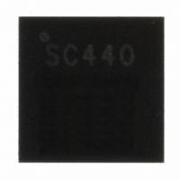
SC440MLTRT Semtech, SC440MLTRT Datasheet - Page 15

SC440MLTRT
Manufacturer Part Number
SC440MLTRT
Description
IC LED DRVR WHITE BCKLGT 24-MLPQ
Manufacturer
Semtech
Type
Backlight, White LEDr
Datasheet
1.SC440MLTRT.pdf
(21 pages)
Specifications of SC440MLTRT
Constant Current
Yes
Topology
PWM, Step-Up (Boost)
Number Of Outputs
6
Internal Driver
Yes
Type - Primary
Backlight
Frequency
640kHz ~ 960kHz
Voltage - Supply
4.5 V ~ 21 V
Voltage - Output
40V
Mounting Type
Surface Mount
Package / Case
24-MLPQ
Current - Output / Channel
30mA
Internal Switch(s)
Yes
Efficiency
91%
Lead Free Status / RoHS Status
Lead free / RoHS Compliant
Operating Temperature
-
Other names
SC440MLTR
Applications Information (continued)
Output Capacitor Selection
The next task in SC440 design is targeting the proper
amount of ripple voltage due to the constant-current
LED loads. The two error amplifiers that control the PWM
converter sense the delta between requested current
and actual current in each output current regulator. On
a cycle-by-cycle basis, a small amount of output ripple
ensures good sensing and tight regulation, while the
output current regulators keep each LED current at a fixed
value. Overall, this allows usage of small output caps while
ensuring precision LED current regulation. Although the
mechanics of regulation and frequency dependence may
be complex, actual selection of output capacitor can be
simplified because this capacitor is mainly selected for
the output ripple of the converter. Assume a ceramic
capacitor is used. The minimum capacitance needed for a
given ripple can be estimated by,
V
During load transient, the output capacitor supplies or
absorbs additional current before the inductor current
reaches its steady state value. Larger capacitance helps
with the overshoot and undershoots during load transient,
and loop stability. Recommended ceramic capacitor
manufacturers are listed in Table 3.
Table 3. Recommended Ceramic Capacitor
Manufacturers
© 2010 Semtech Corp.
RIPPLE
Kemet
Murata
Taiyo Yuden
C
OUT
I
V
V
F
Vendor
– Peak to peak output ripple;
OUT
S
OUT
IN
– Switching frequency.
– Input voltage;
– Output current;
– Boost output voltage;
(V
V
OUT
OUT
F
S
I V
N
V
408-986-0424
814-237-1431
408-573-4150
NOT RECOMMENDED FOR NEW DESIGNS: SEE SC440A
)
RIPPLE
Phone
I
OUT
www.t-yuden.com
www.murata.com
www.kemet.com
Website
Output Rectifying Diode Selection
Schottky diodes are the ideal choice for SC440 due to their
low forward voltage drop and fast switching speed. Table
4 shows several different Schottky diodes that work well
with the SC440. Make sure that the diode has a voltage
rating greater that the possible maximum ouput voltage.
The diode conducts current only when the power switch
is turned off. A diode of 1A will be sufficient for most
designs.
Layout Guidelines
The SC440 contains a boost converter and the placements
of the power components outside the SC440 should follow
the layout guidelines of a general boost converter. The
application circuit on page 17 will be used as an example.
The layout illustration diagram is shown on page 19. R5
and C7 form a decoupling filter for the SC440. C7 should
be placed as close as possible to the VIN and PGND to
achieve the best performance. C6 is the input power
filtering capacitor for the boost converter power train.
L1 is the boost converter input inductor. D1 is the output
rectifying diode and it is recommended that a Schottky
diode be used for fast reverse recovery.
To minimize switching noise for the boost converter, the
output capacitor, C2, should be placed at the bottom, as
displayed on page 19, so that the loop formed by C2, D1,
and the internal switch, is the smallest. The output of the
boost converter is used to power up the LEDs. R6, C9 and
C10 (open, not used), form the compensation network for
the boost converter. C9 should return to analog ground.
Table 4. Recommended Rectifying Diodes
C8 determines the soft-start time and should be connected
to analog ground. R8 is the output current programming
resistor for IO1 through IO6 and should return to analog
ground. IOGND should also be connected to AGND.
Since there is pad at the bottom of the SC440 for heat
dissipation, a copper area right underneath the pad is
used for better heat spreading. On the bottom layer of the
Part
SS13
SS14
www.vishay.com
Vendor
Vishay
www.semtech.com
SC440
15 15


