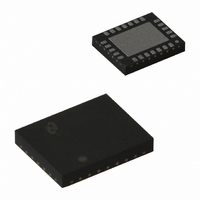
LP3943ISQ/NOPB National Semiconductor, LP3943ISQ/NOPB Datasheet - Page 8

LP3943ISQ/NOPB
Manufacturer Part Number
LP3943ISQ/NOPB
Description
IC LED DRIVER RGB 24-LLP
Manufacturer
National Semiconductor
Series
PowerWise®r
Type
RGB LED Driverr
Datasheet
1.LP3943ISQNOPB.pdf
(13 pages)
Specifications of LP3943ISQ/NOPB
Topology
PWM, Step-Up (Boost)
Number Of Outputs
16
Internal Driver
Yes
Type - Primary
LED Blinker, Light Management Unit (LMU)
Type - Secondary
RGB, White LED
Frequency
400kHz
Voltage - Supply
2.3 V ~ 5.5 V
Mounting Type
Surface Mount
Package / Case
24-LLP
Operating Temperature
-40°C ~ 85°C
Current - Output / Channel
25mA
Internal Switch(s)
Yes
For Use With
LP3943ISQEV - BOARD EVAL FOR LP3943 FUNLIGHT
Lead Free Status / RoHS Status
Lead free / RoHS Compliant
Voltage - Output
-
Efficiency
-
Other names
LP3943ISQ
LP3943ISQTR
LP3943ISQTR
Available stocks
Company
Part Number
Manufacturer
Quantity
Price
Company:
Part Number:
LP3943ISQ/NOPB
Manufacturer:
TI
Quantity:
8 102
Part Number:
LP3943ISQ/NOPB
Manufacturer:
TI/德州仪器
Quantity:
20 000
www.national.com
Application Notes
AUTO INCREMENT
Auto increment is a special feature supported by the LP3943
to eliminate repeated chip and register addressing when
data are to be written to or read from registers in sequential
In the READ mode, when auto increment is enabled, I
master could receive any number of bytes from LP3943
without selecting chip address and register address again.
Every time the I
increment the register address and the next data register will
be read. When I
the register address will roll over to 00H.
In the WRITE mode, when auto increment is enabled, the
LP3943 will increment the register address every time I
2
2
C master reads a register, the LP3943 will
C master reaches the last register (09H),
FIGURE 7. Programming with Auto Increment Disabled (in WRITE Mode)
FIGURE 8. Programming with Auto Increment Enabled (in WRITE Mode)
(Continued)
FIGURE 6. Register Address Byte
2
2
C
C
8
order. The auto increment bit is inside the register address
byte, as shown in Figure 6. Auto increment is enabled when
this bit is programmed to “1” and disabled when it is pro-
grammed to “0”.
Bits 5, 6 and 7 in the register address byte should always be
zero.
master writes to register. When the last register (09H regis-
ter) is reached, the register address will roll over to 02H, not
00H, because the first two registers in LP3943 are read-only
registers. It is possible to write to the first two registers
independently, and the LP3943 will acknowledge, but the
data will be ignored.
If auto increment is disabled, and the I
change register address, it will continue to write data into the
same register.
20079611
20079613
20079612
2
C master does not


