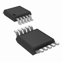
LM3445MM/NOPB National Semiconductor, LM3445MM/NOPB Datasheet - Page 13

LM3445MM/NOPB
Manufacturer Part Number
LM3445MM/NOPB
Description
IC LED DRIVER TRIAC DIMM 10-MSOP
Manufacturer
National Semiconductor
Series
PowerWise®r
Type
Triac Dimmabler
Specifications of LM3445MM/NOPB
Mfg Application Notes
LM3445 Reference Design
Constant Current
Yes
Topology
PWM, Step-Down (Buck)
Number Of Outputs
1
Internal Driver
No
Type - Secondary
High Brightness LED (HBLED)
Frequency
30kHz ~ 1MHz
Voltage - Supply
8 V ~ 12 V
Mounting Type
Surface Mount
Package / Case
10-MSOP, Micro10™, 10-uMAX, 10-uSOP
Operating Temperature
-40°C ~ 125°C
Current - Output / Channel
1A
Internal Switch(s)
Yes
Efficiency
85%
For Use With
LM3445-220VEVAL - BOARD EVAL LM3445 220VLM3445-120VSMEV - BOARD EVAL LM3445 110VLM3445TRIACEVAL - BOARD EVAL LM3445MM
Lead Free Status / RoHS Status
Lead free / RoHS Compliant
Voltage - Output
-
Other names
LM3445MMTR
Available stocks
Company
Part Number
Manufacturer
Quantity
Price
Company:
Part Number:
LM3445MM/NOPB
Manufacturer:
TI
Quantity:
7 000
OVERVIEW OF CONSTANT OFF-TIME CONTROL
A buck converter’s conversion ratio is defined as:
Constant off-time control architecture operates by simply
defining the off-time and allowing the on-time, and therefore
the switching frequency, to vary as either V
The output voltage is equal to the LED string voltage (V
and should not change significantly for a given application.
The input voltage or V
input line varies. The length of the on-time is determined by
the sensed inductor current through a resistor to a voltage
reference at a comparator. During the on-time, denoted by
t
increase. During the on-time, current flows from V
through the LEDs, through L2, Q2, and finally through R3 to
ground. At some point in time, the inductor current reaches a
maximum (I
the ISNS pin. This sensed voltage across R3 is compared
ON
, MOSFET switch Q2 is on causing the inductor current to
L2-PK
) determined by the voltage sensed at R3 and
BUCK
in this analysis will vary as the
FIGURE 11. LM3445 Buck Regulation Circuit
IN
or V
O
changes.
BUCK
LED
),
,
13
against the voltage of dim decoder output, FLTR2, at which
point Q2 is turned off by the controller.
During the off-period denoted by t
continues to flow through the LEDs via D10.
FIGURE 12. Inductor Current Waveform in CCM
30060323
OFF
, the current through L2
www.national.com
30060325


