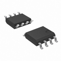
AP8800SG-13 Diodes Inc, AP8800SG-13 Datasheet - Page 3

AP8800SG-13
Manufacturer Part Number
AP8800SG-13
Description
IC LED DRIVER HIGH BRIGHT 8SOIC
Manufacturer
Diodes Inc
Type
HBLED Driverr
Datasheet
1.AP8800M8G-13.pdf
(11 pages)
Specifications of AP8800SG-13
Constant Current
Yes
Topology
PWM, Step-Down (Buck)
Number Of Outputs
1
Internal Driver
Yes
Type - Primary
Backlight
Type - Secondary
High Brightness LED (HBLED)
Frequency
600kHz
Voltage - Supply
8 V ~ 28 V
Voltage - Output
28V
Mounting Type
Surface Mount
Package / Case
8-SOIC (3.9mm Width)
Operating Temperature
-40°C ~ 85°C
Current - Output / Channel
350mA
Internal Switch(s)
Yes
Efficiency
92%
High Level Output Current
350 mA
Operating Supply Voltage
8 V to 28 V
Maximum Supply Current
30 uA
Maximum Operating Temperature
+ 85 C
Mounting Style
SMD/SMT
Minimum Operating Temperature
- 40 C
Lead Free Status / RoHS Status
Lead free / RoHS Compliant
Other names
AP8800SGDITR
Available stocks
Company
Part Number
Manufacturer
Quantity
Price
Company:
Part Number:
AP8800SG-13
Manufacturer:
DIODES
Quantity:
65 000
Note:
Absolute Maximum Ratings
Caution:
Recommended Operating Condition
Electrical Characteristics
Notes:
AP8800
Document number: DS31764 Rev. 5 - 2
I
SW_Leakage
Duty Cycle
Symbol
R
Symbol
Symbol
F
V
V
DS
I
SET
V
T
θ
V
VSW
V
OUT
θ
V
OSC
V
THD
I
REF
T
V
CTRL
LEAD
JA
JC
Q
T
IN
SET
T
(on)
ENH
ENL
ST
IN
J
A
The absolute maximum ratings are rated values exceeding which the product could suffer physical damage.
These values must therefore not be exceeded under any condition.
Semiconductor devices are ESD sensitive and may be damaged by exposure to ESD events.
Suitable ESD precautions should be taken when handling and transporting these devices.
2. For most applications the LED current will be within 8% over the duty cycle range specified. Duty cycle accuracy is also dependent on propagation
3. Refer to figure 5 for the device derating curve.
4. Test condition for SOP-8L, MSOP-8L and DFN3030-10: Device mounted on FR-4 PCB, 2”x2”, 2oz copper, minimum recommended pad layout on
delay. Smaller size inductors can be used but LED current accuracy may be greater than 8% at extremes of duty cycle. This is most noticeable at
low duty cycles (less than 0.1) or when the input voltage is high and only one LED is being driven.
top layer and thermal vias to bottom layer ground plane. For better thermal performance, larger copper pad for heat-sink is needed.
Operating input voltage
Continuous switch current
Quiescient current
Switching frequency
Internal current sense threshold voltage V
Internal reference voltage
SET pin input current
On-resistance of internal switch
Switch pin leakage current
Thermal resistance junction-to-ambient
Thermal resistance junction-to-case
VIN pin voltage
Set voltage relative to V
SW voltage
CTRL pin input voltage
Maximum Junction Temperature
Maximum Lead Temperature
Storage Temperature Range
Ambient Temperature Range
Using Inductor ≥ 100µH (Note 2)
CTRL input voltage to attain 100% LED current
CTRL input voltage below which device turns off
Parameter
Parameter
(V
IN
IN
= 12V, T
Parameter
A
s
= 25°C, unless otherwise specified)
(Note 3)
V
SO-8 (Note 4)
MSOP-8 (Note 4)
DFN3030-10 (Note 4)
SO-8 (Note 4)
MSOP-8 (Note 4)
DFN3030-10 (Note 4)
www.diodes.com
V
IN
SET
IN
-V
-55 to +125
-5 ~ V
=V
SET
-0.3~30
-0.3~30
-0.3 ~ 5
Rating
3 of 11
125
300
IN
-0.1
Conditions
IN
+0.3
350mA LED STEP-DOWN CONVERTER
Unit
°C
°C
°C
V
V
V
V
1.25
Min
-40
0.1
Min
8.0
92
-
-
-
-
-
-
-
-
-
-
-
-
Typ.
0.25
1.25
100
120
1.3
1.7
20
92
46
60
98
32
-
-
-
Max
0.95
0.2
85
Max
350
108
AP8800
2.2
28
30
5
© Diodes Incorporated
-
-
-
-
-
-
-
-
-
March 2011
Unit
ºC
V
°C/W
°C/W
°C/W
°C/W
°C/W
°C/W
MHz
Unit
mA
mV
μA
μA
μA
V
V
Ω


