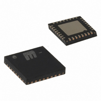
SY88952LMI Micrel Inc, SY88952LMI Datasheet - Page 2

SY88952LMI
Manufacturer Part Number
SY88952LMI
Description
IC LASER DRVR 2.7GBPS 3.6V 32MLF
Manufacturer
Micrel Inc
Type
Laser Diode Driver (Fiber Optic)r
Datasheet
1.SY88952LMG.pdf
(7 pages)
Specifications of SY88952LMI
Number Of Channels
1
Data Rate
2.7Gbps
Voltage - Supply
3 V ~ 3.6 V
Current - Supply
85mA
Current - Modulation
90mA
Current - Bias
100mA
Operating Temperature
-40°C ~ 85°C
Package / Case
32-MLF®, QFN
Mounting Type
Surface Mount
Operating Supply Voltage (min)
3V
Mounting
Surface Mount
Lead Free Status / RoHS Status
Contains lead / RoHS non-compliant
Micrel, Inc.
M9999-082205
hbwhelp@micrel.com or (408) 955-1690
1, 4, 7, 18, 21, 24, 32
PACKAGE/ORDERING INFORMATION
TRUTH TABLE
LATCH
PIN DESCRIPTION
10, 14, 15, 17,
27, 28, 29, EP
19, 20, 22, 23
/CLK
VCC
VCC
VCC
Pin Number
CLK
D
H
X
L
/D
D
32-Pin MLF™ (MLF-32)
5, 6
2, 3
16
11
31
26
25
12
30
13
9
8
1
2
3
4
5
6
7
8
32 31 30 29 28 27 26 25
9 10 11 12 13 14 15 16
/D
H
X
L
(1)
BIASMON
MODMON
Pin Name
BIASMAX
CLK,/CLK
MODSET
LATCH
SLOW
Q, /Q
/FAIL
BIAS
D, /D
VCC
VEE
MD
EN
24
23
22
21
20
19
18
17
EN
H
H
L
VCC
/Q
/Q
VCC
Q
Q
VCC
VEE
Pin Function
Bias Current Output (I
Bias Current Monitor: Sinks current that is proportional to I
path must exist to V
A resistor (R
See “Typical Operating Characteristics” (I
Connect a capacitor (C
Differential Clock Input. 75K pull-down on CLK, 75k pull-up and 75k pull-down on /CLK.
Differential Data Input. 75K pull-down on D, 75k pull-up and 75k pull-down on /D.
TTL Input with 75k pull-up: Default HIGH for normal operation; LOW to disable modulation
current.
TTL Input with 75k pull-up: Default HIGH for latched (clocked) data; LOW for direct data.
Connect this pin to a monitor photodiode anode, a resistor (R
This sets the desired average optical power.
Differential Output: Modulation current output (I
Modulation Current Monitor: Sinks current that is proportional to I
current path must exist to V
A resistor (R
See “Typical Operating Characteristics” (I
TTL Open-Collector Output: Connect a 5k resistor to V
Positive Power Supply.
Device Ground: Ensure the exposed pad is also connected to ground.
OUT
Ordering Information
Notes:
1. Dice are designed to operate from –40 C to +85 C, but are tested and guaranteed to T
2. Tape and Reel.
H
H
L
Part Number
SY88952LMI
SY88952LMITR
SY88952LMG
SY88952LMGTR
(2)
only.
BIASMAX
MODSET
/OUT
H
L
L
CC
) connected to ground sets the modulation current.
) connected to ground sets the maximum bias current.
BIAS
.
(2)
SLOW
(2)
).
2
CC
) to ground to provide a slow-start.
Note 1.
Note 2.
Package
.
MLF-32
MLF-32
MLF-32
MLF-32
Type
(1)
L = LOW, H = HIGH, X = don't care.
H = I
BIAS
MOD
Operating
OUT
Industrial
Industrial
Industrial
Industrial
Range
vs. R
vs. R
MOD
I
MOD_OFF
BIASMAX
MODSET
).
CC
.
Pb-Free bar-line indicator
Pb-Free bar-line indicator
BIAS
).
).
. Indicates APC failure when LOW.
APCSET
, (I
SY88952L with
SY88952L with
MOD
BIAS
SY88952L
SY88952L
Package
Marking
) and a capacitor (C
, (I
/40). An external current
MOD
/45). An external
SY88952L
Pb-Free
Pb-Free
A
APCSET
NiPdAu
NiPdAu
Finish
Sn-Pb
Sn-Pb
Lead
= +25 C
).


