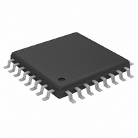
MAX3668EHJ+ Maxim Integrated Products, MAX3668EHJ+ Datasheet - Page 5

MAX3668EHJ+
Manufacturer Part Number
MAX3668EHJ+
Description
IC LSR DRVR 622MBPS 3.63V 32TQFP
Manufacturer
Maxim Integrated Products
Type
Laser Diode Driver (Fiber Optic)r
Datasheet
1.MAX3668EHJ.pdf
(12 pages)
Specifications of MAX3668EHJ+
Data Rate
622Mbps
Number Of Channels
1
Voltage - Supply
3.14 V ~ 5.5 V
Current - Supply
38mA
Current - Modulation
75mA
Current - Bias
80mA
Operating Temperature
-40°C ~ 85°C
Package / Case
32-TQFP, 32-VQFP
Mounting Type
Surface Mount
Package
32TQFP
Number Of Channels Per Chip
1
Operating Supply Voltage
3.14 to 5.5 V
Supply Current
38 mA
Maximum Power Dissipation
929 mW
Mounting Style
SMD/SMT
Lead Free Status / RoHS Status
Lead free / RoHS Compliant
(V
14, 21, 22, 30
CC
1000
1, 2, 6, 15,
5, 7, 8, 10,
12, 13, 26,
17, 20, 24
100
0.1
10
27, 28
1
= +3.3V, T
PIN
11
16
18
19
23
25
29
31
32
1.4
3
4
9
vs. MAXIMUM BIAS SET RESISTOR
1.6
Laser Driver with Automatic Power Control
AVAILABLE BIAS CURRENT
V
A
CC
CLOSED-LOOP OPERATION
V
= +25°C, unless otherwise noted.)
1.8
= +3.3V
CC
BIASMAX
MODSET
= +3.3V, + 5V
ENABLE
APCSET
_______________________________________________________________________________________
R
DATA+
NAME
DATA-
OUT+
CAPC
BIAS
OUT-
GND
BIAS
FAIL
N.C.
V
MD
2.0
CC
(kΩ)
2.2
V
CC
= +5V
2.4
Positive Supply Voltage
Positive PECL Data Input
Negative PECL Data Input
Ground
TTL/CMOS Enable Input. High for normal operation, low to disable laser bias and modulation
currents. Internally pulled high.
TTL Output. Indicates APC failure when low. Internally pulled high through a 6kΩ resistor.
No Connection. Leave unconnected.
Laser Bias Current Output. Isolate from laser with a ferrite bead.
Positive Modulation Current Output. I
Connect this pad to AC coupling network.
Negative Modulation Current Output. I
Connect this pad to V
Monitor Photodiode Connection. Connect this pad to the monitor photodiode anode. A capaci-
tor to ground is required to filter high-speed AC monitor photocurrent.
APC Compensation Capacitor. A 0.1µF capacitor connected from this pad to ground controls
the dominant pole of the automatic power control (APC) feedback loop.
APC Set Resistor. A resistor connected from this pad to ground sets the desired average opti-
cal power. The resulting current is equal to the desired DC monitor diode current. Connect a
100kΩ resistor from this pad to ground if APC is not used.
Modulation Set Resistor. A resistor from this pad to ground sets the laser modulation current.
Maximum Bias Set Resistor. A resistor from this pad to ground sets the maximum laser bias
current. The APC function can subtract from this maximum value but cannot add to it. This
resistor controls the bias-current level when the APC loop is not used.
2.6
Typical Operating Characteristics (continued)
25
20
15
10
5
0
DISTRIBUTION OF MODULATION CURRENT
-25
MODULATION DIODE CURRENT STABILITY (ppm/°C)
T
I
MOD
A
+3.3V, 622Mbps SDH/SONET
= -40°C TO +85°C
= 5mA
65
CC
STABILITY (WORST CASE)
through a 6.3Ω resistor.
155
245
MOD
335
MOD
FUNCTION
flows into this pad when the input signal is high.
425
flows into this pad when the input signal is low.
515
25
20
15
10
DISTRIBUTION OF MONITOR DIODE CURRENT
5
0
MONITOR DIODE CURRENT STABILITY (ppm/°C)
T
I
MD
A
= -40°C TO +85°C
= 18µA
-88
STABILITY (WORST CASE)
Pin Description
-52
20
92
160
5


