DS1862B+ Maxim Integrated Products, DS1862B+ Datasheet - Page 40
DS1862B+
Manufacturer Part Number
DS1862B+
Description
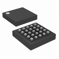
IC LASR CTRLR 7CHAN 5.5V 25CSBGA
Manufacturer
Maxim Integrated Products
Type
Laser Diode Controller (Fiber Optic)r
Datasheet
1.DS1862B.pdf
(43 pages)
Specifications of DS1862B+
Data Rate
10Gbps
Number Of Channels
7
Voltage - Supply
2.9 V ~ 5.5 V
Current - Supply
3mA
Operating Temperature
-40°C ~ 100°C
Package / Case
25-CSBGA
Mounting Type
Surface Mount
Lead Free Status / RoHS Status
Lead free / RoHS Compliant


XFP Laser Control and Digital Diagnostic IC
CRC-8 includes and requires the explicit starting mem-
ory address to be included as the second transferred
byte. Next, the master transfers the data as the DS1862
acknowledges. Only 4 bytes can be sequentially written
during one transmission while using PEC. After the
master writes the intended number of bytes, the CRC-8
value should be transmitted. Following the CRC-8 byte,
the master should transmit the CAB byte (CRC Add-on
Byte). At this point, the DS1862 sends an ACK if the
CRC-8 matches its internal calculated value or a NACK
if not. Finally, the master should end the communication
and send a STOP. See Figure 16 for a graphical repre-
sentation. The CRC-8 is calculated starting with the
MSB of the memory address pointer, number of bytes
to be written, and the written data. The master can then
poll the last ACK or NACK for successful transfer of
written data.
For more information on I
to the XFP and/or SMBus 2.0 standard.
Figure 16. I
40
COMMUNICATIONS KEY
____________________________________________________________________
WRITE UP TO A 4-BYTE PAGE WITH A SINGLE TRANSACTION USING PEC
READ 1–128 BYTES WITH A DUMMY WRITE CYCLE TO SET THE ADDRESS COUNTER
SR
S
P
S
S
2
1 0 1
1 0 1
START
STOP
REPEATED
START
C PEC Communications Examples
0
DATA
DATA
0
A
N
0
0
DATA
0
0
X X X X X X X X
ACK
NOT
ACK
2
0 0
0 0
C PEC communications, refer
A
A
A
A
WHITE BOXES INDICATE THE MASTER IS
CONTROLLING SDA
SHADED BOXES INDICATE THE SLAVE IS
CONTROLLING SDA
MEMORY ADDRESS
MEMORY ADDRESS
A (IF CRC-8 IS CORRECT)
DATA
8-BIT ADDRESS OR DATA
DATA
A
A
A
Before calibrating, the APC register should be set to a
low value to ensure the laser’s maximum power level is
not exceeded before the power level is calibrated.
Additionally, the ER should be set to a minimum value
to ensure that a data test pattern does not cause the
laser to shut off. Once the APC and ER registers are at
minimal values, enable a data pattern and calibrate the
average power level.
While sending data through the laser diode, increase
the value in the APC register until the light output
matches the desired average power level. The average
power level is the arithmetic average of the ‘1’ and ‘0’
power levels.
NUMBER OF BYTES
NUMBER OF BYTES
P
DATA
A
Calibrating APC and Extinction Ratio
CRC-8 VALUE
Applications Information
NOTE:
ALL BYTES ARE SENT MOST SIGNIFICANT BIT FIRST.
THE FIRST BYTE SENT AFTER A START CONDITION IS
ALWAYS THE SLAVE ADDRESS FOLLOWED BY THE
READ/WRITE BIT.
Calibrating the Average Power Level
A
A
A
SR
1 0 1
CRC-8 VALUE
DATA
N
0
P
0
0
0 0
A
A
A
Related parts for DS1862B+
Image
Part Number
Description
Manufacturer
Datasheet
Request
R

Part Number:
Description:
XFP Laser Control and Digital Diagnostic IC
Manufacturer:
Maxim Integrated Products
Part Number:
Description:
MAX7528KCWPMaxim Integrated Products [CMOS Dual 8-Bit Buffered Multiplying DACs]
Manufacturer:
Maxim Integrated Products
Datasheet:
Part Number:
Description:
Single +5V, fully integrated, 1.25Gbps laser diode driver.
Manufacturer:
Maxim Integrated Products
Datasheet:
Part Number:
Description:
Single +5V, fully integrated, 155Mbps laser diode driver.
Manufacturer:
Maxim Integrated Products
Datasheet:
Part Number:
Description:
VRD11/VRD10, K8 Rev F 2/3/4-Phase PWM Controllers with Integrated Dual MOSFET Drivers
Manufacturer:
Maxim Integrated Products
Datasheet:
Part Number:
Description:
Highly Integrated Level 2 SMBus Battery Chargers
Manufacturer:
Maxim Integrated Products
Datasheet:
Part Number:
Description:
Current Monitor and Accumulator with Integrated Sense Resistor; ; Temperature Range: -40°C to +85°C
Manufacturer:
Maxim Integrated Products
Part Number:
Description:
TSSOP 14/A�/RS-485 Transceivers with Integrated 100O/120O Termination Resis
Manufacturer:
Maxim Integrated Products
Part Number:
Description:
TSSOP 14/A�/RS-485 Transceivers with Integrated 100O/120O Termination Resis
Manufacturer:
Maxim Integrated Products
Part Number:
Description:
QFN 16/A�/AC-DC and DC-DC Peak-Current-Mode Converters with Integrated Step
Manufacturer:
Maxim Integrated Products
Part Number:
Description:
TDFN/A/65V, 1A, 600KHZ, SYNCHRONOUS STEP-DOWN REGULATOR WITH INTEGRATED SWI
Manufacturer:
Maxim Integrated Products
Part Number:
Description:
Integrated Temperature Controller f
Manufacturer:
Maxim Integrated Products
Part Number:
Description:
SOT23-6/I�/45MHz to 650MHz, Integrated IF VCOs with Differential Output
Manufacturer:
Maxim Integrated Products
Part Number:
Description:
SOT23-6/I�/45MHz to 650MHz, Integrated IF VCOs with Differential Output
Manufacturer:
Maxim Integrated Products
Part Number:
Description:
EVALUATION KIT/2.4GHZ TO 2.5GHZ 802.11G/B RF TRANSCEIVER WITH INTEGRATED PA
Manufacturer:
Maxim Integrated Products