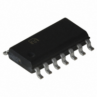
MIC2595-1BM Micrel Inc, MIC2595-1BM Datasheet - Page 23

MIC2595-1BM
Manufacturer Part Number
MIC2595-1BM
Description
IC CTRLR HOT SWAP NEG HV 14-SOIC
Manufacturer
Micrel Inc
Type
Hot-Swap Controllerr
Datasheet
1.MIC2589R-1YM_TR.pdf
(29 pages)
Specifications of MIC2595-1BM
Applications
General Purpose
Internal Switch(s)
No
Voltage - Supply
-19 V ~ -80 V
Operating Temperature
-40°C ~ 85°C
Mounting Type
Surface Mount
Package / Case
14-SOIC (0.154", 3.90mm Width)
Lead Free Status / RoHS Status
Contains lead / RoHS non-compliant
December 2005
higher pulsed power without damage than its
continuous power dissipation ratings imply due to an
inherent trait, thermal inertia.
specification and use of power MOSFETs, the
parameter of interest is the “Transient Thermal
Impedance”, or Z
factor) used as a multiplier of the thermal resistance
(R
“Transient Thermal Impedance Graph”, normalized to
R
versus power pulse duration and duty cycle.
single-pulse curve is appropriate for most hot swap
applications. Z
power
applications.
The following example provides a method for
estimating the peak junction temperature of a power
MOSFET in determining if the MOSFET is suitable for
a
V
the power MOSFET is the SUM110N10-09 (TO-263
package) from Vishay-Siliconix. This MOSFET has an
R
thermal resistance (R
ambient thermal resistance (R
Transient Thermal Impedance Curve is shown in
Figure 8. Consider, say, the MOSFET is switched on
at time t1 and the steady-state load current passing
through the MOSFET is 3A. At some point in time
after t1, at time t2, there is an unexpected short-circuit
applied to the load, causing the MIC2589/MIC2595
controller to adjust the GATE output voltage and
regulate the load current for 20ms at the programmed
current limit value, 4.2A in this example. During this
short-circuit load condition, the dissipation in the
MOSFET is calculated by:
P
P
At first glance, it would appear that a very hefty
MOSFET is required to withstand this extreme
overload condition.
calculation
temperature is not a difficult task. The first step is to
determine
temperature, then add the rise in temperature due to
the maximum power dissipated during a transient
overload caused by a short circuit condition.
equation to estimate the maximum steady-state
junction temperature is given by:
T
T
prior to an overcurrent condition, at which the
MOSFET will operate and is estimated from the
J
C
IN
D
D
θ
ON
(steady-state) ≅ T
θ
, that displays curves for the thermal impedance
(max) is the highest anticipated case temperature,
(short) = V
(short) = 48V × 4.2A = 201.6W for 20ms.
).
(VDD – VEE) = 48V, I
of 9.5mΩ (T
The multiplier is determined using the given
MOSFETs
the
DS
to
θ
× I
is specified from junction-to-case for
particular
θ
approximate
LIM
, which is a real number (variable
maximum
J
C
(max) + ∆T
; V
= 25°C), the junction-to-case
Upon further examination, the
typically
θ(J-C)
DS
LIM
= 0V – (-48V) = 48V
) is 0.4°C/W, junction-to-
= 4.2A, t
θ(J-A)
steady-state
J
the
With respect to the
used
) is 40°C/W, and the
FLT
peak
is 20ms, and
in
application.
telecom
junction
junction
(1)
The
The
23
following equation based on the highest ambient
temperature of the system environment.
T
Let’s assume a maximum ambient of 60°C.
power dissipation of the MOSFET is determined by
the current through the MOSFET and the ON
resistance (I
(specification given at T
example information and substituting into Equation 2,
T
Substituting the variables into Equation 1, T
determined by:
T
Since this is not a closed-form equation, getting a
close approximation may take one or two iterations.
On the second iteration, start with T
value calculated above.
yields;
Another iteration shows that the result (73.63°C) is
converging quickly, so we’ll estimate the maximum
T
The use of the Transient Thermal Impedance Curves
is necessary to determine the increase in junction
temperature associated with a worst-case transient
condition.
maximum power dissipated during a short circuit
event for the MIC2589/MIC2595, we calculate the
transient junction temperature increase as:
T
Assume the MOSFET has been on for a long time –
several minutes or more – and delivering the steady-
state load current of 3A to the load when the load is
short circuited. The controller will regulate the GATE
output voltage to limit the current to the programmed
value of 4.2A for 20ms before immediately shutting off
the output. For this situation and almost all hot swap
applications, this can be considered a single pulse
event as there is no significant duty cycle.
Figure 8, find the point on the X-axis (“Square-Wave
Pulse Duration”) for 25ms, allowing for a 25% margin
T
J
C
C
J(steady-state)
J
(steady-state) ≅T
J
(transient) = P
(max) = T
(max)
(steady-state) ≅66.06°C+[17mΩ+(73.36°C
at 74°C.
= 60°C+[((3A)
= 66.06°C
A
2
From our previous calculation of the
R
(max) + P
≅ 66.06°C+[17mΩ+(66.06°C–25°C)(0.005/°C)
ON
≅ 66.06°C + 7.30°C
≅ 73.36°C
≅73.62°C
C
D
(max)+[R
(short) × R
), which we will estimate at 17mΩ
× (R
×(17mΩ)][(3A)
D
-25°C)×(0.005/°C)
×(17mΩ)][(3A)
ON
× (R
ON
2
+(T
J
×17mΩ)×(40–0.4)°C/W]
Doing so in this example
)][I
θ(J-C)
C
2
θ(J-A)
= 125°C).
×(R
(max)–T
× Multiplier
θ(J-A)
2
– R
×(40–0.4)°C/W]
–R
C
2
×(40–0.4)]°C/W
θ(J-C)
)(0.005)
θ(J-C)
J
(408) 955-1690
)]
M9999-120505
equal to the
)
Using our
(2)
(3)
From
J
The
is


