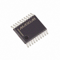
MAX5923EUP+ Maxim Integrated Products, MAX5923EUP+ Datasheet - Page 8

MAX5923EUP+
Manufacturer Part Number
MAX5923EUP+
Description
IC HOT-SWAP SWITCH +60V 20-TSSOP
Manufacturer
Maxim Integrated Products
Series
Simple Swapper™r
Type
Hot-Swap Switchr
Datasheet
1.MAX5923EUPT.pdf
(12 pages)
Specifications of MAX5923EUP+
Applications
General Purpose
Internal Switch(s)
Yes
Current Limit
800mA
Voltage - Supply
16 V ~ 60 V
Operating Temperature
-40°C ~ 85°C
Mounting Type
Surface Mount
Package / Case
20-TSSOP
Product
Controllers & Switches
Supply Voltage (max)
60 V
Supply Voltage (min)
16 V
Power Dissipation
879 mW
Operating Temperature Range
- 40 C to + 85 C
Mounting Style
SMD/SMT
Supply Current
1 mA
Lead Free Status / RoHS Status
Lead free / RoHS Compliant
+60V Simple Swapper Hot-Swap Switch
The MAX5923 is a fully integrated hot-swap switch that
contains a 0.45Ω integrated power MOSFET and oper-
ates from a +16V to +60V supply rail. The device allows
the safe insertion and removal of circuit cards into live
backplanes without causing problematic glitches on the
supply rail. The device also monitors various circuit para-
meters and disconnects the load if a fault condition
occurs, alerting the host with a logic-level FAULT output.
The MAX5923 provides an Enable input to enable/disable
the device with a logic signal and logic output POK that
indicates when the output voltage has reached within
750mV of the input voltage. Three fault conditions are
monitored: a zero-current condition, an overcurrent con-
dition, and a thermal overload condition. A FAULT output
indicates to the host if an overcurrent or thermal fault
occurs and a ZC output indicates if the output has a zero-
current condition. An undervoltage lockout circuitry shuts
down the device if the input voltage falls below the UVLO
threshold.
During power-up, the MAX5923 gradually turns on the
integrated N-channel MOSFET. To minimize EMI, the
MAX5923 limits the output voltage slew rate at the OUT
pin to dV
slew rate out of the OUT pin to dI
The MAX5923 has an integrated 0.45Ω N-channel power
MOSFET. The MOSFET’s drain is connected to the
DRAIN pin and its source is connected to the OUT pin.
The MAX5923 monitors and provides current-limit protec-
tion to the load at all times. The current limit is program-
mable using an external current-sensing resistor
8
_______________________________________________________________________________________
PIN
13
14
15
16
17
20
OUT
/dt = 100V/ms (max) and the output current
LATCH
ZC_EN
NAME
DGND
VDIG
OUT
EN
Detailed Description
Digital Ground. DGND can vary ±4V from AGND. DGND and AGND must be connected together at a
single point in the system.
Fault Management Selection Digital Input. Referenced to DGND. Connect to logic high to latch off
after a fault condition. Connect to logic low for automatic restart after a fault condition (see the Fault
Management section).
Zero-Current Detection Enable Logic Input. Referenced to DGND. Connect ZC_EN to a logic high to
enable the zero-current detection circuitry. Connect ZC_EN to a logic low to disable this function.
ON/OFF Control-Logic Input. Referenced to DGND. Connect to logic high to enable the device.
Connect to logic low to disable the device and reset a latched-off condition.
Digital Supply Voltage. VDIG is the supply voltage for the internal digital logic circuity. EN, LATCH,
and ZC_EN input logic thresholds are automatically scaled to the voltage on VDIG. See the Typical
Application Circuit for proper filtering.
Output Voltage
OUT
Power-Up Mode
/dt = 35A/ms (max).
connected from IN to DRAIN. The MAX5923 features cur-
rent-limit foldback and duty-cycle limit to ensure robust
operation during load-fault and short-circuit conditions
(see the Overcurrent Protection section).
When V
t
ed, the MAX5923 activates the zero-current detection
function. This function monitors the output for an under-
current condition and eventually turns off the power to
the output if the load is disconnected (see the Zero-
Current Detection section).
The MAX5923 operates from a +16V to +60V supply
voltage range and has a default UVLO set at +28V. The
UVLO threshold is adjustable using a resistive divider
connected to the UVLO pin (see Figure 1). When the
input voltage is below the UVLO threshold, all operation
stops and the MOSFET is held off. When the input volt-
age is above the UVLO threshold and EN is high, the
MAX5923 goes into operation.
To adjust the UVLO threshold, connect an external
resistive divider from IN to UVLO and then from UVLO
to AGND. Use the following equation to calculate the
new UVLO threshold:
V
50kΩ (min), so keep the R1 and R2 parallel combination
value at least 20 times smaller than 50kΩ to minimize
the new UVLO threshold error.
POK_HIGH
REF
is typically 1.33V. The UVLO pin input resistance is
FUNCTION
OUT
, POK goes open-drain. After POK is assert-
Pin Description (continued)
is within 750mV of V
V
UVLO TH
Undervoltage Lockout (UVLO)
_
=
V
REF
1
+
R
R
IN
1
2
for more than


