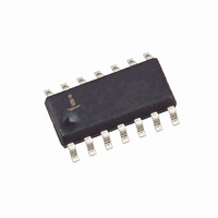
ISL6142IBZA Intersil, ISL6142IBZA Datasheet - Page 14

ISL6142IBZA
Manufacturer Part Number
ISL6142IBZA
Description
IC CTRLR HOT PLUG NEG 14-SOIC
Manufacturer
Intersil
Type
Hot-Swap Controllerr
Datasheet
1.ISL6142CBZA.pdf
(23 pages)
Specifications of ISL6142IBZA
Applications
General Purpose, VoIP
Internal Switch(s)
No
Voltage - Supply
36 V ~ 72 V
Operating Temperature
-40°C ~ 85°C
Mounting Type
Surface Mount
Package / Case
14-SOIC (0.154", 3.90mm Width)
Lead Free Status / RoHS Status
Lead free / RoHS Compliant
Applications Information
Typical Values for a representative
system; which assumes:
43V to 71V supply range; 48 nominal; UV = 43V; OV = 71V
1A of typical current draw; 2.5 Amp Over-Current
100µF of load capacitance (CL); equivalent RL of 48Ω
(R = V/I = 48V/1A)
R1: 0.02Ω (1%)
R2: 10Ω (5%)
R3: 18kΩ (5%)
R4: 549kΩ (1%)
R5: 6.49kΩ (1%)
R6: 10kΩ (1%)
R7/R8: 400Ω (1%)
R9: 4.99KΩ (1%)
R10: 5.10KΩ (10%)
C1: 150nF (25V)
C2: 3.3nF (100V)
C3: 1500pF (25V)
Q1: IRF530 (100V, 17A, 0.11Ω)
Q2: N-Channel logic FET
Logic
Supply
-48V IN
R10
Q2
GND
ADC
14
FIGURE 29. TYPICAL APPLICATION WITH MINIMUM COMPONENTS
R9
R4
R5
R6
FAULT
DIS
IS
UV
OV
CT
ISL6142, ISL6152
OUT
C3
V
EE
IS-
R7
R1
Quick Guide to Choosing Component
Values
(See fig 29 for reference)
This section will describe the minimum components needed
for a typical application, and will show how to select
component values. Note that “typical” values may only be
good for this application; the user may have to select
alternate component values to optimize performance for
other applications. Each block will then have more detailed
explanation of how the device works, and alternatives.
R4, R5, R6 - together set the Under-Voltage (UV) and Over-
Voltage (OV) trip points. When the power supply ramps up
and down, these trip points (and their hysteresis) will
determine when the GATE is allowed to turn on and off (UV
and OV do not control the PWRGD / PWRGD output). The
input power supply is divided down such that when the
voltage on the OV pin is below its threshold and the UV pin is
above its threshold their comparator outputs will be in the
proper state signaling the supply is within its desired
operating range, allowing the GATE to turn on. The
equations below define the comparator thresholds for an
increasing (in magnitude) supply voltage.
R8
V
V
IS+
OV
UV
ISL6142
=
=
SENSE GATE
---------------------------------------- -
V
---------------------------------------- -
〈
〈
R
R
DD
(
4
4
R
+
+
5
(
C1
R
R
R
+
6
5
5
R
)
+
+
6
R
R
)
Q1
6
6
〉
〉
R2
×
×
1.255
1.255
R3 C2
PWRGD
DRAIN
-48V OUT
GND
RL
CL
(EQ. 2)
(EQ. 1)


