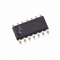
HIP1012ACBZA-T Intersil, HIP1012ACBZA-T Datasheet - Page 12

HIP1012ACBZA-T
Manufacturer Part Number
HIP1012ACBZA-T
Description
IC CTRLRL HOT PLUG DUAL 14-SOIC
Manufacturer
Intersil
Type
Hot-Swap Controllerr
Datasheet
1.HIP1012ACBZA.pdf
(15 pages)
Specifications of HIP1012ACBZA-T
Applications
General Purpose
Internal Switch(s)
No
Voltage - Supply
10.5 V ~ 13.2 V
Operating Temperature
0°C ~ 70°C
Mounting Type
Surface Mount
Package / Case
14-SOIC (0.154", 3.90mm Width)
Lead Free Status / RoHS Status
Lead free / RoHS Compliant
GENERIC BOARD
LOAD BOARD
BUS BOARD
SW12 and RL2
SW13 and RL3
SW14 and RL4
DESIGNATOR
SW11 and RL1
COMPONENT
QxB and QxC
LED2, LED3
TP1 - TP14
P1 - P2
Q1, Q2
R
C
LED1
JP1
JP2
JP3
JP4
3
3
W1
U1
R
R
R
R*
C
C
C
, R
, C
1
2
5
1
2
5
4
4
HIP1012CB or HIP1012ACB
RF1K49156, Si4404DY
NOT POPULATED
5V Sense Resistor
3.3V/12V Sense Resistor
Loop compensation Resistors
Current Limit Set Resistor
Isolation resistor (not provided, see Decoupling
Concerns in Critical Items section)
Gate Timing Capacitors
Charge Pump Capacitor
Time-out Set Capacitor
Vdd decoupling capacitor
Jumper to configure PWRON2
Jumper to configure VDD
Jumper to configure Charge Pump Cap
Jumper to configure PWRON1
Pgood indicator
NOT PROVIDED
Test Points for HIP1012 pin 1 to pin 14
Edge connector fingers
5V high load (7Ω)
5V low load (10Ω)
3.3V high load (0.8Ω)
3.3V low load (1.6Ω)
Load “HOT” indicators
12
COMPONENT NAME
TABLE 5. HIP1012EVAL1 BOARD COMPONENT LISTING
HIP1012A
Intersil Corporation, Dual Power Controller
N-Channel MOSFET in 8 SOIC or equivalent replacement
Mounting areas for additional 8 SOIC
MOSFETs
100mΩ, 1%, Metal Strip current sensing resistor
20mΩ, 1%, Metal Strip current sensing resistor
20Ω, Resistor in series with gate capacitor. This RC may be necessary
to provide current loop stability. Keep resistor < 50Ω.
10kΩ, Current limit = ~10µA x (R
Add resistor (<50Ω) to isolate V
eliminate random V
0.01µF, 10µA charging I source provides slow ramp on of N-Channel
MOSFETs
0.1µF, Charge Pump Capacitor necessary for +12V and +5V
operation.
0.047µF, Provides ~9ms of time-out period prior to latch off during
which IOC can be resolved. The duration of current limit time-out (in
seconds) = 200kΩ x C
0.1µF, Provides V
See Table 3 for jumper configuration descriptions
Lit indicates a fault condition
Tie point for dedicated +12V HIP1012 supply, use in default
configuration
Modify edge connector finger lengths for power sequencing
Switch and load resistor pair to invoke high current load on 5V
Switch and load resistor pair to invoke low current load on 5V
Switch and load resistor pair to invoke high current load on 3.3V
Switch and load resistor pair to invoke low current load on 3.3V
Lit indicates N-Channel MOSFETs are on and loads are HOT
Bus interconnect board
DD
COMPONENT DESCRIPTION
DD
decoupling
TIM
low reset. Cut short to install.
(Farads).
DD
ILIM
from load transients if necessary to
/ R
, DPAK or D
SENSE
).
2
PAK packaged


