LTC4241IGN#PBF Linear Technology, LTC4241IGN#PBF Datasheet - Page 12

LTC4241IGN#PBF
Manufacturer Part Number
LTC4241IGN#PBF
Description
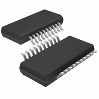
IC CTRLR HOTSWAP 3.3V AUX 20SSOP
Manufacturer
Linear Technology
Type
Hot-Swap Controllerr
Datasheet
1.LTC4241CGN.pdf
(16 pages)
Specifications of LTC4241IGN#PBF
Applications
PCI, PCI-X
Internal Switch(s)
No
Voltage - Supply
3.3V, 5V, ±12V
Operating Temperature
-40°C ~ 85°C
Mounting Type
Surface Mount
Package / Case
20-SSOP (0.154", 3.91mm Width)
Lead Free Status / RoHS Status
Lead free / RoHS Compliant
LTC4241
APPLICATIO S I FOR ATIO
For C
TIMER pin is immediately pulled low when ON goes low.
Thermal Shutdown
The internal switches for the 12V and –12V supplies are
protected by an internal current limit and thermal shut-
down circuit. When the temperature of the chip reaches
150 C, only the switches controlling the PCI supplies will
be latched off and the FAULT pin will be pulled low.
Short-Circuit Protection for PCI Power Supplies
During a normal power-up sequence for the PCI power
supplies, if the TIMER is done ramping and any supply is
still in current limit, all of the pass transistors will be
immediately turned off, the TIMER and FAULT pin will be
pulled low as shown in Figure 4.
If a short-circuit occurs after the PCI supplies are powered
up, the shorted supply’s current will drop immediately to
the limit value (Figure 5).
If the supply remains in current limit for more than 17 s,
all of the PCI supplies except the 3.3V auxiliary supply will
be latched off. The 17 s delay prevents quick current
12
TIMER
5V
3V
Figure 4. Power-Up into a Short on 3.3V Output
OUT
OUT
10V/DIV
10V/DIV
10V/DIV
10V/DIV
10V/DIV
PWRGD
12V
V
5V/DIV
5V/DIV
5V/DIV
5V/DIV
TIMER
FAULT
= 0.1 F, the timer period will be ~50ms. The
EEOUT
GATE
OUT
ON
U
U
20ms/DIV
W
4241 F04
U
spikes — for example, from a fan turning on — from
causing false trips of the circuit breaker. The chip will stay
in the latched-off state until the ON pin is cycled low then
high, or the 12V
To prevent excessive power dissipation in the pass tran-
sistors and to prevent voltage spikes on the supplies
during short-circuit conditions, the current limit on each
PCI supply, except the 3.3V auxiliary supply, is designed
to be a function of the output voltage. As the output voltage
drops, the current limit decreases. Unlike a traditional
circuit breaker function where huge currents can flow
before the breaker trips, the current foldback feature
assures that the supply current will be kept at a safe level
and prevent voltage glitches when powering up into a
short.
The current limit and the foldback current level for the 5V
and 3.3V outputs are both a function of the external sense
resistor (R1 for 5V
shown in Figure 1, a sense resistor is connected between
5V
sense resistor is connected between 3V
Figure 5. Short-Circuit on 5V Followed by Circuit Breaker Reset
IN
and 5V
5V
3V
OUT
OUT
10V/DIV
10V/DIV
10V/DIV
10V/DIV
10V/DIV
PWRGD
12V
SENSE
V
5V/DIV
5V/DIV
5V/DIV
TIMER
5V/DIV
FAULT
EEOUT
GATE
OUT
ON
IN
OUT
for the 5V supply. For the 3V supply, a
supply is cycled.
and R2 for 3V
20ms/DIV
OUT
, see Figure 1). As
IN
and 3V
4241 F05
sn4241 4241f
SENSE
.


