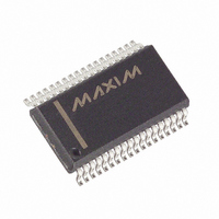
MAX5952AEAX+ Maxim Integrated Products, MAX5952AEAX+ Datasheet - Page 21

MAX5952AEAX+
Manufacturer Part Number
MAX5952AEAX+
Description
IC PSE CNTRLR FOR POE 36-SSOP
Manufacturer
Maxim Integrated Products
Type
Power Over Ethernet Controller (PoE)r
Datasheet
1.MAX5952AUAX.pdf
(50 pages)
Specifications of MAX5952AEAX+
Applications
Remote Peripherals (Industrial Controls, Cameras, Data Access)
Internal Switch(s)
No
Operating Temperature
-40°C ~ 85°C
Mounting Type
Surface Mount
Package / Case
36-BSOP (0.300", 7.5mm Width)
Product
Controllers & Switches
Supply Voltage (max)
5.5 V
Supply Voltage (min)
1.71 V
Power Dissipation
941 mW
Operating Temperature Range
- 40 C to + 85 C
Mounting Style
SMD/SMT
Supply Current
4.8 mA
Input Voltage
60V
Digital Ic Case Style
SSOP
No. Of Pins
36
Uvlo
28.5V
Frequency
400kHz
Interface
I2C
Termination Type
SMD
Rohs Compliant
Yes
Filter Terminals
SMD
Controller Type
Power Over Ethernet PD
Lead Free Status / RoHS Status
Lead free / RoHS Compliant
V
ranges from +3.0V to +5.5V and determines the logic
thresholds for the CMOS connections (SDAIN,
SDAOUT, SCL, AUTO, SHD_, A_). This voltage range
enables the MAX5952 to interface with a nonisolated
low-voltage microcontroller. The MAX5952 checks the
digital supply for compatibility with the internal logic.
The MAX5952 also features a V
(V
MAX5952 in reset and the ports shut off. Bit 0 in the
supply event register shows the status of V
(Table 12) after V
outputs reference to DGND. DGND and AGND must be
connected together externally. Connect DGND to
AGND at a single point in the system as close as possi-
ble to the MAX5952.
SHD_ shuts down the respective ports without using
the serial interface. Hardware shutdown offers an emer-
gency turn-off feature that allows a fast disconnect of
the power supply from the port. Pull SHD_ low to
remove power. SHD_ also resets the corresponding
events and status register bits.
The MAX5952 contains an open-drain logic output (INT)
that goes low when an interrupt condition exists. R00h
and R01h (Tables 6 and 7) contain the definitions of the
interrupt registers. The mask register R01h determines
events that trigger an interrupt. As a response to an inter-
rupt, the controller reads the status of the event register
to determine the cause of the interrupt and takes subse-
quent actions. Each interrupt event register also contains
a Clear on Read (CoR) register. Reading through the
CoR register address clears the interrupt. INT remains
low when reading the interrupt through the read-only
addresses. For example, to clear a startup fault on the
port 4 read address 09h (see Table 11). Use the global
pushbutton bit in register 1Ah (bit 7, Table 23) to clear
interrupts, or use a software or hardware reset.
The MAX5952 contains several undervoltage and over-
voltage protection features. Table 12 in the Register
Map and Description section shows a detailed list of
the undervoltage and overvoltage protection features.
An internal V
keeps the MOSFET off and the MAX5952 in reset until
V
nal V
ports when (V
DD
AGND
DDUVLO
supplies power for the internal logic circuitry. V
EE
- V
overvoltage (V
) of +2.0V. A V
EE
EE
exceeds 29V for more than 3ms. An inter-
AGND
undervoltage lockout (V
DD
______________________________________________________________________________________
has recovered. All logic inputs and
- V
EE_OV
EE
Overvoltage Protection
DDUVLO
) exceeds 60V. The digital
Hardware Shutdown
) circuit shuts down the
DD
Undervoltage and
undervoltage lockout
High-Power, Quad, PSE Controller
condition keeps the
Digital Logic
EEUVLO
Interrupt
DDUVLO
) circuit
DD
for Power-Over-Ethernet
supply also contains an undervoltage lockout
(V
undervoltage and overvoltage interrupts: V
age interrupt (V
(V
fault latches into the supply events register (Table 12),
but the MAX5952 does not shut down the ports with
V
Setting R13h[DCD_EN_] bits high enable DC load moni-
toring during a normal powered state. If V
across R
V
and asserts the LD_DISC_ bit of the corresponding port.
The MAX5952 features AC load disconnect monitoring.
Connect an external sine wave to OSC. The oscillator
requirements are:
1) V
2) Positive peak voltage > +2V
3) Frequency > 60Hz
A 100Hz ±10%, 2V
+2.2V typical) is recommended.
The MAX5952 buffers and amplifies 3x the external
oscillator signal and sends the signal to DET_, where
the sine wave is AC-coupled to the output. The
MAX5952 senses the presence of the load by monitor-
ing the amplitude of the AC current returned to DET_
(see the Functional Diagram ).
Setting R13h[ACD_EN_] bits high enable AC load dis-
connect monitoring during a normal powered state. If
the AC current peak at the DET_ input falls below I
for more than t
asserts the LD_DISC_ bit of the corresponding port.
I
An internal comparator checks for a proper amplitude
of the oscillator input. If the positive peak of the input
sinusoid falls below a safety value of 2V, OSC_FAIL
sets and the port shuts down. Power cannot be applied
to the ports when ACD_EN is set high and OSC_FAIL is
set high. Leave OSC unconnected or connect it to
DGND when not using AC-disconnect detection.
If the MAX5952 die temperature reaches +150°C, an
overtemperature fault generates and the MAX5952
shuts down. The MOSFETs turn off. The die tempera-
ture of the MAX5952 must cool down below 130°C to
remove the overtemperature fault condition. After a
thermal shutdown, the part is reset.
ACTH
EEUV
DCTH
DDUVLO
DDUV
P-P
, V
is programmable using R23h[0-3].
, for more than t
), and V
S
x Frequency = 200V
DDUV
) falls below the DC load disconnect threshold,
). The MAX5952 also features three other
, or V
DISC
DD
EEUV
P-P
DDOV
overvoltage interrupt (V
, the device turns off power and
DC Disconnect Monitoring
AC Disconnect Monitoring
±5%, with +1.2V offset (V
), V
DISC
.
DD
, the device turns off power
P-P
undervoltage interrupt
Thermal Shutdown
x Hz ±15%
RS
EE
(the voltage
undervolt-
DDOV
PEAK
ACTH
). A
21
=


