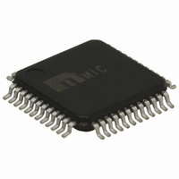
MIC2593-2YTQ Micrel Inc, MIC2593-2YTQ Datasheet - Page 14

MIC2593-2YTQ
Manufacturer Part Number
MIC2593-2YTQ
Description
IC CTRLR HOTPLUG PCI DUAL 48TQFP
Manufacturer
Micrel Inc
Type
Hot-Swap Controllerr
Datasheet
1.MIC2593-2YTQ.pdf
(26 pages)
Specifications of MIC2593-2YTQ
Applications
PCI, PCI-X
Internal Switch(s)
No
Voltage - Supply
3.3V, 5V, ±12V
Operating Temperature
0°C ~ 70°C
Mounting Type
Surface Mount
Package / Case
48-TQFP
Lead Free Status / RoHS Status
Lead free / RoHS Compliant
Other names
576-1100
Available stocks
Company
Part Number
Manufacturer
Quantity
Price
General Purpose Input (GPI) Pins
Two pins on the MIC2593 are available for use as GPI
pins. The logic state of each of these pins can be
determined by polling Bits [4:5] of Common Status
Register. Both of these inputs are compliant to 3.3V. If
unused, connect the GPI[A/B] pins to GND.
Fault Reporting and /INT Interrupt Generation
SMI-only Control Applications
In applications where the MIC2593 is controlled only by
the SMI, the ON[A/B] and AUXEN[A/B] should be
connected to GND as shown in Figure 6. In this case, the
MIC2593’s /FAULT[A/B] outputs and STAT[A/B] Register
Bit D[7] (FAULT[A/B]) are not activated, as fault status is
determined by polling STAT[A/B] Register Bits D[4:0] and
CS (Common Status) Register Bits D[2:1]. Individual fault
bits in STAT[A/B] and CS are asserted after power-on-
reset when
Either or both CNTRL[A/B] Register Bits D[1:0] are
asserted,
AND
Micrel, Inc.
September 2008
•
•
•
12VIN[A/B], 12MVIN[A/B], 5VIN[A/B], 3VIN[A/B],
or VSTBY[A/B] input voltage is lower than its
respective ULVO threshold, OR
The fast OC circuit breaker[A/B] has tripped, OR
The slow OC circuit breaker[A/B] has tripped
AND its filter timeout has expired, OR
MAIN_OUT[A/B]
AUX_OUT[A/B]
/FAULT_[A/B]
AUXEN[A/B]
I
MAIN_OUT[A/B]
I
AUX_OUT[A/B]
VSTBY
ON[A/B]
/INT*
0
0
0
0
0
0
0
0
I
I
I
I
STEADY-STATE
STEADY-STATE
LIM(AUX)
LIM(MAIN)
Figure 8. Hot Plug Interface Mode Operation
UVLO
t POR
+3.3V
V
IH
t FLT
V
IL
* /INT de-asserted by software
*
14
V
IH
To clear any one or all STAT[A/B] Register Bits D[4:0]
and/or CS Register Bits D[2:1] once asserted, a software
subroutine can perform an “echo reset” where a Logical
“1” is written back to those register bit locations that have
indicated a fault.
The open-drain, active-LOW /INT output signal is
activated after power-on-reset when the INTMSK bit (CS
Register Bit D[3]) has been reset to Logical “0”. Once
activated, the /INT output is asserted by any one of the
fault conditions listed above and de-asserted when one or
all STAT[A/B] Register Bits D[4:0] and/or CS Register Bits
D[2:1] are reset upon the execution of an SMBus “echo
reset” WRITE_BYTE cycle.
HPI-only Control Applications
In applications where the MIC2593 is controlled only by
the HPI, SMBus signals SCL, SDA, and /INT signals are
connected to VSTBY as shown in Figure 6. In this
configuration, the MIC2593’s /FAULT[A/B] outputs are
activated after power-on-reset and become asserted
when:
•
•
V
IH
The slow OC circuit breaker[A/B] has tripped
AND Slot[A/B] die temperature exceeds 140°C,
OR
The MIC2593’s global die temperature exceeds
160°C
t FLT
V
IL
*
V
IH
M9999-092208
MIC2593


