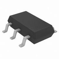
LTC4210-1CS6#TRMPBF Linear Technology, LTC4210-1CS6#TRMPBF Datasheet - Page 9

LTC4210-1CS6#TRMPBF
Manufacturer Part Number
LTC4210-1CS6#TRMPBF
Description
IC CONTROLLER HOT SWAP TSOT23-6
Manufacturer
Linear Technology
Type
Hot-Swap Controllerr
Datasheet
1.LTC4210-1CS6TRMPBF.pdf
(20 pages)
Specifications of LTC4210-1CS6#TRMPBF
Applications
General Purpose
Internal Switch(s)
No
Voltage - Supply
2.7 V ~ 16.5 V
Operating Temperature
0°C ~ 70°C
Mounting Type
Surface Mount
Package / Case
SOT-23-6 Thin, TSOT-23-6
Input Voltage
17V
Output Voltage
3V
Internal Switch
No
Rohs Compliant
Yes
Lead Free Status / RoHS Status
Lead free / RoHS Compliant
Other names
LTC4210-1CS6#TRMPBFTR
Available stocks
Company
Part Number
Manufacturer
Quantity
Price
APPLICATIO S I FOR ATIO
Current Limit Circuit Breaker Function
The LTC4210 features a current limiting circuit breaker
instead of a traditional comparator circuit breaker. When
there is a sudden load current surge, such as a low
impedance fault, the bus supply voltage can drop signifi-
cantly to a point where the power to an adjacent card is
affected, causing system malfunctions. The LTC4210 fast
response error amplifier (EA) instantly limits current by
reducing the external MOSFET GATE pin voltage. This
minimizes the bus supply voltage drop and permits power
budgeting and fault isolation without affecting neighbor-
ing cards. A compensation circuit should be connected to
the GATE pin for current limit loop stability.
Sense Resistor Consideration
The nominal fault current limit is determined by a sense
resistor connected between V
given by Equation 1.
The power rating of the sense resistor should be rated at
the fault current level. Table 2 in the Appendix lists some
common sense resistors.
For proper circuit breaker operation, Kelvin-sense PCB
connections between the sense resistor and the LTC4210
V
drawing in Figure 1 illustrates the connections between
the LTC4210 and the sense resistor. PCB layout should be
balanced and symmetrical to minimize wiring errors. In
addition, the PCB layout for the sense resistor should
include good thermal management techniques for optimal
sense resistor power dissipation.
CC
I
LIMIT NOM
and SENSE pins are strongly recommended. The
(
)
R
SENSE NOM
V
U
CB NOM
(
(
U
)
)
CC
R
and the SENSE pin as
W
SENSE NOM
50
mV
(
)
U
(1)
Calculating Current Limit
For a selected R
Equation 1. The minimum load current is given by
Equation 2:
where
The maximum load current is given by Equation 3:
where
TRACK WIDTH W:
ON 1 OZ COPPER
0.03" PER AMP
I
R
I
R
Figure 1. Making PCB Connections to the Sense Resistor
LIMIT MIN
LIMIT MAX
SENSE MAX
SENSE MIN
(
(
(
(
CURRENT FLOW
)
)
)
TO LOAD
)
SENSE
R
LTC4210-1/LTC4210-2
R
W
SENSE MAX
R
R
SENSE MIN
V
V
SENSE
CB MIN
CB MAX
SENSE
, the nominal load current is given by
(
(
(
(
•
)
• 1
)
SENSE RESISTOR
)
)
– 1
V
TO
CC
R
R
R
R
100
100
TOL
SENSE MAX
SENSE MIN
SENSE
TOL
56
TO
44
mV
mV
(
(
CURRENT FLOW
)
TO LOAD
)
421012f
4210 F01
9
(2)
(3)


