ADE7755ARS Analog Devices Inc, ADE7755ARS Datasheet - Page 2
ADE7755ARS
Manufacturer Part Number
ADE7755ARS
Description
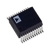
IC ENERGY METERING 24-SSOP
Manufacturer
Analog Devices Inc
Datasheet
1.ADE7755ARSZRL.pdf
(20 pages)
Specifications of ADE7755ARS
Rohs Status
RoHS non-compliant
Input Impedance
390 KOhm
Measurement Error
0.1%
Voltage - I/o High
2.4V
Voltage - I/o Low
0.8V
Current - Supply
3mA
Voltage - Supply
4.75 V ~ 5.25 V
Operating Temperature
-40°C ~ 85°C
Mounting Type
Surface Mount
Package / Case
24-SSOP (0.200", 5.30mm Width)
Meter Type
Single Phase
For Use With
EVAL-ADE7755ZEB - BOARD EVALUATION FOR AD7755
Lead Free Status / RoHS Status
Not Compliant
Available stocks
Company
Part Number
Manufacturer
Quantity
Price

Part Number:
ADE7755ARS
Manufacturer:
ADI/亚德诺
Quantity:
20 000
Company:
Part Number:
ADE7755ARS/ADE7755
Manufacturer:
Panasonic
Quantity:
200
Part Number:
ADE7755ARSRL
Manufacturer:
ADI/亚德诺
Quantity:
20 000
Part Number:
ADE7755ARSZ
Manufacturer:
ADI/亚德诺
Quantity:
20 000
Company:
Part Number:
ADE7755ARSZ-RL
Manufacturer:
TI
Quantity:
230
Company:
Part Number:
ADE7755ARSZRL
Manufacturer:
FREESCALE
Quantity:
430


ADE7755
TABLE OF CONTENTS
Features .............................................................................................. 1
General Description ......................................................................... 1
Functional Block Diagram .............................................................. 1
Revision History ............................................................................... 2
Specifications ..................................................................................... 3
Absolute Maximum Ratings ............................................................ 5
Pin Configuration and Function Descriptions ............................. 6
Typical Performance Characteristics ............................................. 8
Terminology .................................................................................... 11
Theory of Operation ...................................................................... 12
REVISION HISTORY
8/09—Rev. 0 to Rev. A
Changes to Format ............................................................. Universal
Changes to Features Section and General Description Section . 1
Moved Figure 2 ................................................................................. 4
Changes to Pin 22, Pin 23, and Pin 24 Descriptions, Table 4 ..... 7
Changes to Terminology Section.................................................. 11
Changes to Theory of Operation Section, Figure 22, Power
Factor Considerations Section, and Figure 23 ............................ 12
Changes to Nonsinusoidal Voltage and Current Section and
Analog Inputs Section .................................................................... 13
Changes to Figure 27 ...................................................................... 14
Changes to HPF and Offset Effects Section, Figure 29, and
Digital-to-Frequency Conversion Section .................................. 15
Changes to Figure 32 ...................................................................... 16
Changes to Transfer Function Section ......................................... 17
Changes to Selecting a Frequency for an Energy Meter
Application Section ........................................................................ 18
Changes to No Load Threshold Section ...................................... 19
Updated Outline Dimensions ....................................................... 20
Changes to Ordering Guide .......................................................... 20
5/02—Revision 0: Initial Version
Timing Characteristics ................................................................ 4
ESD Caution .................................................................................. 5
Power Factor Considerations .................................................... 12
Nonsinusoidal Voltage and Current ........................................ 13
Rev. A | Page 2 of 20
Outline Dimensions ....................................................................... 20
Analog Inputs ............................................................................. 13
Typical Connection Diagrams .................................................. 14
Power Supply Monitor ............................................................... 14
Digital-to-Frequency Conversion ............................................ 15
Interfacing the ADE7755 to a Microcontroller for Energy
Measurement ............................................................................... 16
Power Measurement Considerations ....................................... 16
Transfer Function ....................................................................... 17
Selecting a Frequency for an Energy Meter Application ...... 18
Frequency Outputs ..................................................................... 18
No Load Threshold .................................................................... 19
Ordering Guide .......................................................................... 20
Related parts for ADE7755ARS
Image
Part Number
Description
Manufacturer
Datasheet
Request
R

Part Number:
Description:
±1.7g Dual-Axis IMEMS Accelerometer Evaluation Board
Manufacturer:
Analog Devices Inc
Datasheet:

Part Number:
Description:
Inertial Sensor Evaluation System
Manufacturer:
Analog Devices Inc
Datasheet:
Part Number:
Description:
Manufacturer:
Analog Devices Inc
Datasheet:
Part Number:
Description:
Manufacturer:
Analog Devices Inc
Datasheet:
Part Number:
Description:
Manufacturer:
Analog Devices Inc
Datasheet:
Part Number:
Description:
Manufacturer:
Analog Devices Inc
Datasheet:
Part Number:
Description:
Manufacturer:
Analog Devices Inc
Datasheet:
Part Number:
Description:
Manufacturer:
Analog Devices Inc
Datasheet:
Part Number:
Description:
Manufacturer:
Analog Devices Inc
Datasheet:
Part Number:
Description:
Manufacturer:
Analog Devices Inc
Datasheet:
Part Number:
Description:
Manufacturer:
Analog Devices Inc
Datasheet:
Part Number:
Description:
Manufacturer:
Analog Devices Inc
Datasheet:
Part Number:
Description:
Manufacturer:
Analog Devices Inc
Datasheet: