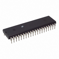
MM58241N National Semiconductor, MM58241N Datasheet - Page 3

MM58241N
Manufacturer Part Number
MM58241N
Description
IC DISPLAY DRIVER HI VOLT 40-DIP
Manufacturer
National Semiconductor
Datasheet
1.MM58241N.pdf
(8 pages)
Specifications of MM58241N
Display Type
Vacuum Fluorescent (VF)
Configuration
Alphanumeric or Dot Matrix
Interface
Serial
Current - Supply
150µA
Voltage - Supply
4.5 V ~ 5.5 V
Operating Temperature
-40°C ~ 85°C
Mounting Type
Through Hole
Package / Case
40-DIP (0.600", 15.24mm)
Lead Free Status / RoHS Status
Contains lead / RoHS non-compliant
Digits Or Characters
-
Other names
*MM58241N
Available stocks
Company
Part Number
Manufacturer
Quantity
Price
Company:
Part Number:
MM58241N
Manufacturer:
AD
Quantity:
2 650
Part Number:
MM58241N
Manufacturer:
NS/国半
Quantity:
20 000
Figure 2 shows the pinout of the MM58241 device where
AC Electrical Characteristics
Note 2 For timing purposes the signals ENABLE and BLANK can be considered to be totally independent of each other
Note 3 AC input waveform specification for test purposes t
Note 4 Clock input rise and fall times must not exceed 5 s
Connection Diagrams
Functional Description
This product is specifically designed to drive multiplexed or
non-multiplexed high voltage alphanumeric or dot matrix
vacuum fluorescent (VF) displays Character generation is
done externally in the microprocessor with a serial data
path to the display driver The MM58421 uses three signals
DATA IN CLOCK and ENABLE where ENABLE acts as an
external load signal Display blanking can be achieved by
means of the BLANKING CONTROL input and a logic ‘1’
will turn off all sections of the display A block diagram of
the MM58241 is shown in Figure 1
output 1 (pin 18) is equivalent to bit 1 i e the first bit of data
Symbol
f
t
t
t
t
t
t
t
C
H
L
DS
DH
ES
EH
CDO
Order Number MM58241N or MM58241V
See NS Package Number N40A or V44A
Dual-In-Line Package
Clock Input
Data Input
Enable Input
Data Output
Frequency
High Time
Low Time
Set-Up Time
Hold Time
Set-Up Time
Hold Time
CLOCK Low to Data Out
Time
FIGURE 2
Top View
Parameter
r
T
t
TL F 5600 – 2
f s
A
e b
20 ns f
(Notes 3 and 4)
C
L
Conditions
40 C to
e
e
50 pF
800 kHz 50%
3
a
to be loaded into the shift register following ENABLE high A
logic ‘1’ at the input will turn on the corresponding display
digit segment dot output
A significant reduction in discrete board components can be
achieved by use of the MM58241 because external pull-
down resistors are not required Due to the nature of the
output stage both its on and off impedance values vary as a
function of the display voltage applied However Figures 3a
and 3b show that this output impedance will remain con-
stant for a fixed value of display voltage
85 C V
g
DD
10% duty cycle
e
Min
300
300
100
100
100
100
5V
Plastic Chip Carrier
g
0 5V
Top View
Typ
Max
800
500
TL F 5600 – 8
Units
kHz
ns
ns
ns
ns
ns
ns
ns


