MM5451N National Semiconductor, MM5451N Datasheet - Page 2
MM5451N
Manufacturer Part Number
MM5451N
Description
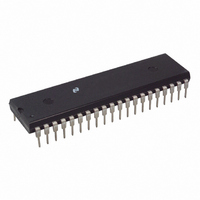
IC LED DISPLAY DRIVER 40DIP
Manufacturer
National Semiconductor
Datasheet
1.MM5450N.pdf
(8 pages)
Specifications of MM5451N
Display Type
LED
Configuration
7 Segment
Interface
Serial
Digits Or Characters
4 or 5 Digits
Current - Supply
7mA
Voltage - Supply
4.75 V ~ 11 V
Operating Temperature
-25°C ~ 85°C
Mounting Type
Through Hole
Package / Case
40-DIP (0.600", 15.24mm)
Lead Free Status / RoHS Status
Contains lead / RoHS non-compliant
Other names
*MM5451N
Available stocks
Company
Part Number
Manufacturer
Quantity
Price
Company:

Part Number:
MM5451N
Manufacturer:
LINEAR
Quantity:
10 566


Absolute Maximum Ratings
If Military Aerospace specified devices are required
please contact the National Semiconductor Sales
Office Distributors for availability and specifications
Voltage at Any Pin
Operating Temperature
Storage Temperature
Junction Temperature
Lead Temperature (Soldering 10 sec )
Electrical Characteristics
Note 1 Output matching is calculated as the percent variation (I
Note 2 With a fixed resistor on the brightness input pin some variation in brightness will occur from one device to another Maximum brightness input current can
be 2 mA as long as Note 3 and junction temperature equation are complied with
Note 3 See Figures 5 6 and 7 for Recommended Operating Conditions and limits Absolute maximum for each output should be limited to 40 mA
Note 4 The V
Note 5 AC input waveform specification for test purpose t
Note 6 Clock input rise and fall times must not exceed 300 ns
Connection Diagrams
Power Supply
Power Supply Current
Input Voltages
Brightness Input (Note 2)
Output Sink Current
Brightness Input Voltage (Pin 19)
Output Matching (Note 1)
Clock Input
Data Input
Data Enable Input
Logical ‘‘0’’ Level (V
Logical ‘‘1’’ Level (V
Segment OFF
Segment ON
Frequency f
High Time t
Low Time t
Set-Up Time t
Hold Time t
Set-Up Time t
Parameter
OUT
l
h
DH
C
voltage should be regulated by the user See Figures 6 and 7 for allowable V
DS
DES
Dual-In-Line Package
L
H
)
)
FIGURE 2a
Top View
Order Number MM5450N MM5451N MM5450V or MM5451V
V
SS
b
Excluding Output Loads
4 75V
V
V
V
Brightness Input
Brightness Input
Brightness Input
Input Current 750 mA
(Notes 5 and 6)
g
0 3V to V
b
DD l
OUT
OUT
10 mA Input Bias
b
See NS Package Number N40A or V44A
65 C to
T
25 C to
A
e
e
s
5 25V
within operating range V
Conditions
r s
3 0V
1V (Note 3)
V
DD s
SS
TL F 6136 – 2
20 ns t
MAX
a
a
a
a
150 C
150 C
300 C
5 25V
e
e
e
85 C
a
12V
f s
0 mA
100 mA
750 mA
I
MIN
20 ns f
) 2
2
e
Power Dissipation at
500 kHz 50%
Molded DIP Package Board Mount
Molded DIP Package Socket Mount
Molded DIP Package socket mount i
Derate 18 5 mW C above 25 C
Molded DIP Package board mount i
DD
Derate 20 4 mW C above 25 C
V
e
DD
b
4 75V to 11 0V V
4 75
Min
950
950
300
300
100
OUT
2 2
2 0
3 0
15
0
0
0 3
b
2V
vs I
g
10% duty cycle
OUT
operation
Dual-In-Line Package
a
25 C
Typ
SS
2 7
FIGURE 2b
Top View
e
0V unless otherwise specified
Max
0 75
g
V
V
500
0 8
4 3
11
10
10
25
JA
7
DD
DD
4
20
JA
e
e
49 C W
54 C W
TL F 6136–3
2 3W
Units
2 5W
kHz
mA
mA
mA
mA
mA
mA
%
ns
ns
ns
ns
ns
V
V
V
V
V
Related parts for MM5451N
Image
Part Number
Description
Manufacturer
Datasheet
Request
R

Part Number:
Description:
National Semiconductor [8-Bit D/A Converter]
Manufacturer:
National Semiconductor
Datasheet:
Part Number:
Description:
National Semiconductor [Media Coprocessor]
Manufacturer:
National Semiconductor
Datasheet:
Part Number:
Description:
Digitally Controlled Tone and Volume Circuit with Stereo Audio Power Amplifier, Microphone Preamp Stage and National 3D Sound
Manufacturer:
National Semiconductor
Datasheet:
Part Number:
Description:
Digitally Controlled Tone and Volume Circuit with Stereo Audio Power Amplifier, Microphone Preamp Stage and National 3D Sound
Manufacturer:
National Semiconductor
Datasheet:
Part Number:
Description:
AC97 Rev 2 Codec with Sample Rate Conversion and National 3D Sound
Manufacturer:
National Semiconductor
Part Number:
Description:
Manufacturer:
National Semiconductor
Datasheet:
Part Number:
Description:
Manufacturer:
National Semiconductor
Datasheet:
Part Number:
Description:
General Purpose, Low Voltage, Low Power, Rail-to-Rail Output Operational Amplifiers
Manufacturer:
National Semiconductor
Datasheet:
Part Number:
Description:
8-bit 20 MSPS flash A/D converter.
Manufacturer:
National Semiconductor
Datasheet:
Part Number:
Description:
Low Noise Quad Operational Amplifier
Manufacturer:
National Semiconductor
Datasheet:
Part Number:
Description:
Quad Differential Line Receivers
Manufacturer:
National Semiconductor
Datasheet:
Part Number:
Description:
Quad High Speed Trapezoidal? Bus Transceiver
Manufacturer:
National Semiconductor
Datasheet:
Part Number:
Description:
Dual Line Receiver
Manufacturer:
National Semiconductor
Datasheet:
Part Number:
Description:
TTL to 10k ECL Level Translator with Latch
Manufacturer:
National Semiconductor
Datasheet: