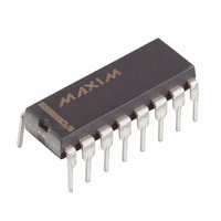
MAX6959AAPE+ Maxim Integrated Products, MAX6959AAPE+ Datasheet - Page 10

MAX6959AAPE+
Manufacturer Part Number
MAX6959AAPE+
Description
IC DRVR DSPL LED 16-DIP
Manufacturer
Maxim Integrated Products
Datasheet
1.MAX6958AAEE.pdf
(19 pages)
Specifications of MAX6959AAPE+
Display Type
LED
Configuration
7 Segment + 2 Annunciators
Interface
SMBus (2-Wire/I²C)
Digits Or Characters
4 Digits
Current - Supply
5.9mA
Voltage - Supply
3 V ~ 5.5 V
Operating Temperature
-40°C ~ 125°C
Mounting Type
Through Hole
Package / Case
16-DIP (0.300", 7.62mm)
Number Of Digits
4
Number Of Segments
36
Low Level Output Current
275 mA
High Level Output Current
30 mA
Operating Supply Voltage
3 V to 5.5 V
Maximum Supply Current
6.7 mA
Maximum Power Dissipation
842 mW
Maximum Operating Temperature
+ 125 C
Mounting Style
Through Hole
Minimum Operating Temperature
- 40 C
Lead Free Status / RoHS Status
Lead free / RoHS Compliant
The digit registers and segments register use 1 bit to
set the state of one segment. Each bit is high to turn a
segment on, or low to turn it off (Table 6).
The decode-mode register sets hexadecimal code
(0–9, A–F) or no-decode operation for each digit. Each
bit in the register corresponds to one digit. Logic high
selects hexadecimal decoding while logic low bypass-
es the decoder. Digits can be set for decode or no
decode in any combination. Bit assignment and exam-
ples of the decode mode control register format are
shown in Table 7.
2-Wire Interfaced, 3V to 5.5V, 4-Digit,
9-Segment LED Display Drivers with Keyscan
Table 5. No-Decode Mode Data Bits and Corresponding Segment Lines
Table 6. No-Decode Mode Data Bits and
Corresponding Segment Lines
Table 7. Decode-Mode Register Examples
10
Bit assignment for each digit
No decode for digits 3–0
Hexadecimal decode for digit
0; no decode for digits 3–1
Hexadecimal decode for digits
2–0; no decode for digit 3
Hexadecimal decode for digit
3; no decode for digits 2–0
Hexadecimal decode for digits
3–0
DIGIT/SEGMENT REGISTER
______________________________________________________________________________________
REGISTER BIT
DECODE MODE
Segments
Digit 0
Digit 1
Digit 2
Digit 3
0
1
—
—
Decode-Mode Register
CODE (HEX)
CODE (HEX)
ADDRESS
ADDRESS
SEGMENT BEHAVIOR
0x01
0x01
0x01
0x01
0x01
0x01
0x20
0x21
0x22
0x23
0x24
—
—
Segment off
Segment on
D7
—
—
X
X
X
X
X
X
SEG 7
D7
X
X
X
X
D6
—
—
X
X
X
X
X
X
SEG a
SEG a
SEG a
SEG a
SEG 6
D6
In hexadecimal code-decode mode, the decoder looks
only at the lower nibble of the data in the digit register
(D3–D0), disregarding bits D7–D4. Table 7 lists the hexa-
decimal code font. When no decode is selected, data
bits D7–D0 correspond to the segment lines of the
MAX6958/MAX6959. Table 8 shows the one-to-one pair-
ing of each data bit to the appropriate segment line.
On initial power-up, all control registers are reset, the
display is blanked, and the MAX6958/MAX6959 enter
shutdown mode (Table 9). At power-up, the MAX6958/
MAX6959 are initially set to scan four digits, do not
decode data in the digit registers or scan key switches
(MAX6959 only), and the intensity register is set to a
low value (4/64 intensity).
D5
—
—
X
X
X
X
X
X
SEG b
SEG b
SEG b
SEG b
SEG 5
D5
REGISTER DATA
D4
—
—
X
X
X
X
X
X
REGISTER DATA
SEG c
SEG c
SEG c
SEG c
SEG 4
D4
Digit 3
D3
—
—
0
0
0
1
1
SEG d
SEG d
SEG d
SEG d
SEG 3
D3
Digit 2
D2
—
—
0
0
1
0
1
SEG e
SEG e
SEG e
SEG e
SEG 2
Digit 1
D2
D1
—
—
0
0
1
0
1
Initial Power-Up
SEG 1
SEG f
SEG f
SEG f
SEG f
Digit 0
D1
D0
—
—
0
1
1
0
1
SEG g
SEG g
SEG g
SEG g
SEG 0
CODE
0xX0
0xX1
0xX7
0xX8
0xXF
HEX
D0
—
—
—


