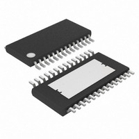
MAX7456EUI+T Maxim Integrated Products, MAX7456EUI+T Datasheet - Page 22

MAX7456EUI+T
Manufacturer Part Number
MAX7456EUI+T
Description
IC DISPLAY 1CH W/EEPROM 28TSSOP
Manufacturer
Maxim Integrated Products
Type
OSD (On-Screen Display) Video Generatorr
Datasheet
1.MAX7456EUI.pdf
(44 pages)
Specifications of MAX7456EUI+T
Applications
Security Systems, Video Routing
Mounting Type
Surface Mount
Package / Case
28-TSSOP Exposed Pad, 28-eTSSOP, 28-HTSSOP
Current - Supply
58mA
Voltage - Supply
4.75 V ~ 5.25 V
Operating Temperature
-40°C ~ 85°C
Interface
SPI Serial
Display Type
OSD
Digits Or Characters
256 Characters
Lead Free Status / RoHS Status
Lead free / RoHS Compliant
Configuration
-
Lead Free Status / Rohs Status
Details
Single-Channel Monochrome On-Screen
Display with Integrated EEPROM
Figure 19. Writing Character Address Byte in 8-Bit and 16-Bit
Operation Modes
Figure 20. Reading Character Address and Character Attribute Bytes in 16-Bit Operation Mode
Figure 21. Write Operation in Auto-Increment Mode
22
SCLK
SDIN
CS
______________________________________________________________________________________
1
0
2
SCLK
SDIN
0
CS
3
0
4
0
MSB
SDOUT
D7 D6 D5 D4 D3 D2 D1 D0
5
SCLK
1
SDIN
0
CS
6
2
1
7
1
1
3
1
8
1
2
4
0
MSB
3
5
1
C
9
A
7
4
1
6
10 11 12 13 14 15 16
C
A
X
6
5
X
7
C
A
5
LSB
6
X
8
C
A
4
7
X
C
A
3
8
X
C
A
2
MSB
C
A
1
C
A
7
9
C
A
0
LSB
C
A
6
10 11 12 13 14 15 16
C
A
5
C
A
4
C
A
3
C
A
2
The MAX7456’s power-on reset circuitry (POR) pro-
vides an internal reset signal that is active after the sup-
ply voltage has stabilized. The internal reset signal
resets all registers to their default values and clears the
display memory. The register reset process requires
100µs, and to avoid unexpected results, read/write
activity is not allowed during this interval. The display
memory is reset, and the OSD is enabled typically
50ms after the supply voltage has stabilized and a sta-
ble 27MHz clock is available. The user should avoid
SPI operations during this time to avoid unexpected
results. After 50ms (typical), STAT[6] can be polled to
verify that the reset sequence is complete (Figure 22).
C
A
1
LSB
C
A
0
MSB
0
1
B
C
L
2
B
K
L
3
N
V
I
4
0
5
0
6
0
7
8
LSB
0
Power-On Reset
Resets


