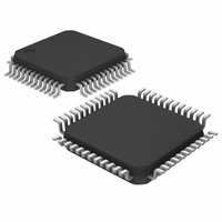
MAX1365ECM+T Maxim Integrated Products, MAX1365ECM+T Datasheet - Page 15

MAX1365ECM+T
Manufacturer Part Number
MAX1365ECM+T
Description
IC PANEL METER 4.5 DIG 48LQFP
Manufacturer
Maxim Integrated Products
Datasheet
1.MAX1367ECM.pdf
(25 pages)
Specifications of MAX1365ECM+T
Display Type
LED
Configuration
7 Segment
Digits Or Characters
A/D 4.5 Digits
Voltage - Supply
2.7 V ~ 5.25 V
Operating Temperature
-40°C ~ 85°C
Mounting Type
Surface Mount
Package / Case
48-LQFP
Lead Free Status / RoHS Status
Lead free / RoHS Compliant
Current - Supply
-
Interface
-
Set EN_BPM high to engage bipolar operation. In bipo-
lar mode, the current output at 4–20OUT (4–20mA or
0 to 16mA) maps the analog input voltage (±2V or
±200mV). In bipolar mode, a 0V analog input maps to
midscale (12mA). See Table 5 for current output (see
Figures 12 and 13).
The MAX1365/MAX1367 feature a 5.2V linear regulator.
The 5.2V regulator consists of an op amp and connec-
tions to an external depletion-mode FET. The 5.2V regu-
lator regulates the loop voltage that powers the
voltage-to-current converter and the rest of the trans-
mitter circuitry. The regulator output voltage is available
at REG_VDD and is given by the equation:
Figure 6. Strain-Gauge Application with the MAX1365/MAX1367
Table 5. Current Output Table
Negative Full Scale
0V
Positive Full Scale
5.2V Linear Regulator with Compensation
ANALOG INPUT
V
REG_VDD
______________________________________________________________________________________
Stand-Alone, 4.5-/3.5-Digit Panel Meters
UNIPOLAR MODE
= 2.54 x V
DUMMY
ACTIVE
GAUGE
GAUGE
(EN_I = LOW)
16
0
0
0.1µF
R
REF+
REF
R
R
10µF
Bipolar Mode
0.1µF
0.1µF
0.1µF
UNIPOLAR MODE
0.1µF
(EN_I = HIGH)
REF+
REF-
AIN+
AIN-
AV
20
4
4
DD
ANALOG SUPPLY
CURRENT OUTPUT (mA)
MAX1365
MAX1367
FERRITE
The FET breakdown and saturation voltages determine
the usable range of loop voltages (V
FET parameters such as V
ductance must be chosen so that the op amp output on
the REG_FORCE pin can control the FET operating
point while swinging in the range from VREG_AMP to
REG_VDD. See the Selecting Depletion-Mode FET sec-
tion in the Applications Information section.
Connect a 0.1µF capacitor between CMP and
REG_FORCE to ensure stable operation of the regulator.
At power-on, the digital filter and modulator circuits
reset. The MAX1365 allows 6s for the reference to sta-
bilize before performing enhanced offset calibration.
GND
BEAD
4-20OUT
DV
with 4–20mA Output
NEGV
DD
0.1µF
BIPOLAR MODE
(EN_I = LOW)
4–20mA/0 TO 16mA
CURRENT-LOOP
OUTPUT
Applications Information
10µF
16
0
8
GS
(off), I
Power-On Reset
BIPOLAR MODE
DSS
EXT
(EN_I = HIGH)
, and transcon-
). The external
12
20
4
15


