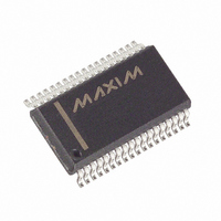
MAX6957AAX+ Maxim Integrated Products, MAX6957AAX+ Datasheet - Page 20

MAX6957AAX+
Manufacturer Part Number
MAX6957AAX+
Description
IC DRVR DSPL LED 36-SSOP
Manufacturer
Maxim Integrated Products
Datasheet
1.MAX6957ANI.pdf
(25 pages)
Specifications of MAX6957AAX+
Display Type
LED
Configuration
7, 16, 20 Segment
Interface
4-Wire Serial
Current - Supply
180µA
Voltage - Supply
2.5 V ~ 5.5 V
Operating Temperature
-40°C ~ 125°C
Mounting Type
Surface Mount
Package / Case
36-SSOP
Number Of Digits
7
Number Of Segments
28
Low Level Output Current
18000 uA
Operating Supply Voltage
2.5 V to 5.5 V
Maximum Supply Current
230 uA
Maximum Power Dissipation
941 mW
Maximum Operating Temperature
+ 125 C
Mounting Style
SMD/SMT
Minimum Operating Temperature
- 40 C
No. Of Segments
28
Supply Voltage Range
2.5V To 5.5V
Driver Case Style
SSOP
No. Of Pins
36
Operating Temperature Range
-40°C To +125°C
Device Type
LED
Termination Type
SMD
Rohs Compliant
Yes
Filter Terminals
SMD
Lead Free Status / RoHS Status
Lead free / RoHS Compliant
Digits Or Characters
-
Lead Free Status / Rohs Status
Lead free / RoHS Compliant
4-Wire-Interfaced, 2.5V to 5.5V, 20-Port and
28-Port LED Display Driver and I/O Expander
The MAX6957’s SPI interface is guaranteed to operate at
26Mbps on a 2.5V supply, and on a 5V supply typically
operates at 50Mbps. This means that the transmission
line issues should be considered when the interface con-
nections are longer that 100mm, particularly with higher
supply voltages. Ringing manifests itself as communica-
tion issues, often intermittent, typically due to double
clocking due to ringing at the SCLK input. Fit a 1kΩ to
10kΩ parallel termination resistor to either GND or V+ at
the DIN, SCLK, and CS input to damp ringing for moder-
ately long interface runs. Use line impedance matching
terminations when making connections between boards.
Ensure that all the MAX6957 GND connections are
used. A ground plane is not necessary, but may be
20
______________________________________________________________________________________
TOP VIEW
PC Board Layout Considerations
DOUT
GND
GND
ISET
P12
P13
P10
P11
P15
P16
P17
P18
P19
P20
P21
P14
P8
P9
SPI Routing Considerations
10
11
12
13
14
15
16
17
18
1
2
3
4
5
6
7
8
9
MAX6957
SSOP
36
35
34
33
32
31
30
29
28
27
26
25
24
23
22
21
19
20
V+
CS
DIN
SCLK
P4
P31
P5
P30
P6
P29
P7
P28
P27
P26
P25
P24
P23
P22
useful to reduce supply impedance if the MAX6957
outputs are to be heavily loaded. Keep the track length
from the ISET pin to the R
sible, and take the GND end of the resistor either to the
ground plane or directly to the GND pins.
The MAX6957 operates with power-supply voltages of
2.5V to 5.5V. Bypass the power supply to GND with a
0.047µF capacitor as close to the device as possible.
Add a 1µF capacitor if the MAX6957 is far away from
the board's input bulk decoupling capacitor.
TRANSISTOR COUNT: 30,316
PROCESS: CMOS
P12
P13
P10
P14
P11
P15
P16
P17
P8
P9
Pin Configurations (continued)
10
1
2
3
4
5
6
7
8
9
Power-Supply Considerations
MAX6957
TQFN
ISET
Chip Information
resistor as short as pos-
30
29
28
27
26
25
24
23
22
21
P4
P31
P5
P30
P6
P29
P7
P28
P27
P26


