LM98555CCMH/NOPB National Semiconductor, LM98555CCMH/NOPB Datasheet - Page 7
LM98555CCMH/NOPB
Manufacturer Part Number
LM98555CCMH/NOPB
Description
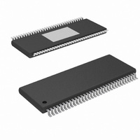
IC CCD DRIVER 64-TSSOP
Manufacturer
National Semiconductor
Datasheet
1.LM98555CCMHXNOPB.pdf
(10 pages)
Specifications of LM98555CCMH/NOPB
Display Type
Charge-Coupled Device (CCD)
Voltage - Supply
3 V ~ 5.5 V
Operating Temperature
0°C ~ 70°C
Mounting Type
Surface Mount
Package / Case
64-TSSOP Exposed Pad, 64-eTSSOP, 64-HTSSOP
Lead Free Status / RoHS Status
Lead free / RoHS Compliant
Current - Supply
-
Interface
-
Configuration
-
Digits Or Characters
-
Other names
LM98555CCMH


Application Information
The LM98555 is a fully integrated clock driver/buffer for high
speed CCD applications. It provides high performance low
impedance drivers, with optimized low skew performance of
the P1 and P2 outputs. Enable inputs allow use of two, four,
six, or all eight P1 and P2 drivers to optimize the amount of
drive for the application. The 64 pin thermally enhanced
TSSOP provides excellent power handling through the use of
an exposed heat transfer pad on the underside of the pack-
age.
THERMAL GUIDELINES
The LM98555's maximum power dissipation limit, shown in
the Operating Conditions section, must be strictly adhered to.
The product's multiple high-strength drivers, with their ability
to drive a wide-range of loads, make it possible to be within
spec on each output and yet violate the aggregate maximum
power dissipation limit for the total product. Special caution
must be paid to this by limiting the chip's operating conditions
(loads, power supply, number of parallel drivers enabled, fre-
quency of operation) to make certain that the maximum power
dissipation limit is never exceeded.
Thermal characterization of the device has been done to pro-
vide reference points under specific conditions. θ junction to
ambient was measured using a 5.5 inch by 3 inch, 4 layer
PCB. The thermal contact pad on the board was connected
using vias to a full ground plane on one of the internal layers.
The recommended thermal pad is shown in Figure 4.
FIGURE 5. 4 Layer PCB - Example 1
FIGURE 6. 4 Layer PCB - Example 2
FIGURE 7. 2 Layer PCB
7
The vias shown provide a path for heat to flow from the pad
to a heat sinking or dissipating area of the printed circuit
board. The following figures show several typical examples of
how this can be done, and illustrate how heat is conducted
away from the IC to larger areas where it is dissipated.
FIGURE 4. Exposed Pad Land Pattern
20126407
20126409
20126408
20126406
www.national.com
Related parts for LM98555CCMH/NOPB
Image
Part Number
Description
Manufacturer
Datasheet
Request
R

Part Number:
Description:
National Semiconductor [8-Bit D/A Converter]
Manufacturer:
National Semiconductor
Datasheet:
Part Number:
Description:
National Semiconductor [Media Coprocessor]
Manufacturer:
National Semiconductor
Datasheet:
Part Number:
Description:
Digitally Controlled Tone and Volume Circuit with Stereo Audio Power Amplifier, Microphone Preamp Stage and National 3D Sound
Manufacturer:
National Semiconductor
Datasheet:
Part Number:
Description:
Digitally Controlled Tone and Volume Circuit with Stereo Audio Power Amplifier, Microphone Preamp Stage and National 3D Sound
Manufacturer:
National Semiconductor
Datasheet:
Part Number:
Description:
AC97 Rev 2 Codec with Sample Rate Conversion and National 3D Sound
Manufacturer:
National Semiconductor
Part Number:
Description:
Manufacturer:
National Semiconductor
Datasheet:
Part Number:
Description:
Manufacturer:
National Semiconductor
Datasheet:
Part Number:
Description:
General Purpose, Low Voltage, Low Power, Rail-to-Rail Output Operational Amplifiers
Manufacturer:
National Semiconductor
Datasheet:
Part Number:
Description:
8-bit 20 MSPS flash A/D converter.
Manufacturer:
National Semiconductor
Datasheet:
Part Number:
Description:
Low Noise Quad Operational Amplifier
Manufacturer:
National Semiconductor
Datasheet:
Part Number:
Description:
Quad Differential Line Receivers
Manufacturer:
National Semiconductor
Datasheet:
Part Number:
Description:
Quad High Speed Trapezoidal? Bus Transceiver
Manufacturer:
National Semiconductor
Datasheet:
Part Number:
Description:
Dual Line Receiver
Manufacturer:
National Semiconductor
Datasheet:
Part Number:
Description:
TTL to 10k ECL Level Translator with Latch
Manufacturer:
National Semiconductor
Datasheet: