LM3914V/NOPB National Semiconductor, LM3914V/NOPB Datasheet - Page 16
LM3914V/NOPB
Manufacturer Part Number
LM3914V/NOPB
Description
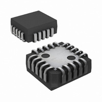
IC DRIVER DOT BAR DISPLAY 20PLCC
Manufacturer
National Semiconductor
Datasheet
1.LM3914VXNOPB.pdf
(22 pages)
Specifications of LM3914V/NOPB
Display Type
LED, LCD, Vacuum Fluorescent
Configuration
Dot/Bar Display
Digits Or Characters
10 Steps
Current - Supply
6.1mA
Voltage - Supply
3 V ~ 20 V
Operating Temperature
0°C ~ 70°C
Mounting Type
Surface Mount
Package / Case
20-PLCC
Led Driver Application
Bar-Graph Meter, Expanded Scale Meter
No. Of Outputs
10
Output Current
30mA
Output Voltage
1.34V
Input Voltage
3V To 15V
Dimming Control Type
Analog
Rohs Compliant
Yes
Lead Free Status / RoHS Status
Lead free / RoHS Compliant
Interface
-
Lead Free Status / Rohs Status
RoHS Compliant part
Other names
*LM3914V
LM3914V
LM3914V
Available stocks
Company
Part Number
Manufacturer
Quantity
Price
Company:

Part Number:
LM3914V/NOPB
Manufacturer:
TI
Quantity:
445
Company:
Part Number:
LM3914V/NOPB
Manufacturer:
Texas Instruments
Quantity:
10 000


www.national.com
Application Hints
APPLICATION TIPS FOR THE LM3914 ADJUSTABLE
REFERENCE
Greatly Expanded Scale (Bar Mode Only)
Placing the LM3914 internal resistor divider in parallel with a
section (.230Ω) of a stable, low resistance divider greatly
reduces voltage changes due to IC resistor value changes
with temperature. Voltage V
by use of R2. Then the voltage V
can be adjusted to 200mV, using R5 without affecting V
LED current will be approximately 10mA.
Adjusting Linearity Of Several Stacked
dividers
Three internal voltage dividers are shown connected in se-
ries to provide a 30-step display. If the resulting analog meter
is to be accurate and linear the voltage on each divider must
be adjusted, preferably without affecting any other adjust-
ments. To do this, adjust R2 first, so that the voltage across
R5 is exactly 1V. Then the voltages across R3 and R4 can
be independently adjusted by shunting each with selected
resistors of 6kΩ or higher resistance. This is possible be-
cause the reference of LM3914 No. 3 is acting as a constant
current source.
1
should be trimmed to 1.1V first
(Continued)
2
across the IC divider string
Greatly Expanded Scale (Bar Mode Only)
1
.
16
Non-Interacting Adjustments For Expanded Scale
Meter (4.5V to 5V, Bar or Dot Mode)
This arrangement allows independent adjustment of LED
brightness regardless of meter span and zero adjustments.
First, V
across R4) can be adjusted to exactly 0.5V using R6 without
affecting the previous adjustment.
R9 programs LED currents within a range of 2.2mA to 20mA
after the above settings are made.
The references associated with LM3914s No. 1 and No. 2
should have their Ref Adj pins (pin 8) wired to ground, and
their Ref Outputs loaded by a 620Ω resistor to ground. This
makes available similar 20mA current outputs to all the LEDs
in the system.
If an independent LED brightness control is desired (as in
the previous application), a unity gain buffer, such as the
LM310, should be placed between pin 7 and R1, similar to
the previous application.
1
is adjusted to 5V, using R2. Then the span (voltage
00797015
Related parts for LM3914V/NOPB
Image
Part Number
Description
Manufacturer
Datasheet
Request
R

Part Number:
Description:
IC, DOT/BAR DISPLAY DRIVER, LCC-20
Manufacturer:
National Semiconductor
Datasheet:

Part Number:
Description:
Audio Power Driver (discontinued)
Manufacturer:
National Semiconductor Corporation
Datasheet:
Part Number:
Description:
National Semiconductor [8-Bit D/A Converter]
Manufacturer:
National Semiconductor
Datasheet:
Part Number:
Description:
National Semiconductor [Media Coprocessor]
Manufacturer:
National Semiconductor
Datasheet:
Part Number:
Description:
Digitally Controlled Tone and Volume Circuit with Stereo Audio Power Amplifier, Microphone Preamp Stage and National 3D Sound
Manufacturer:
National Semiconductor
Datasheet:
Part Number:
Description:
Digitally Controlled Tone and Volume Circuit with Stereo Audio Power Amplifier, Microphone Preamp Stage and National 3D Sound
Manufacturer:
National Semiconductor
Datasheet:
Part Number:
Description:
AC97 Rev 2 Codec with Sample Rate Conversion and National 3D Sound
Manufacturer:
National Semiconductor
Part Number:
Description:
Manufacturer:
National Semiconductor
Datasheet:
Part Number:
Description:
Manufacturer:
National Semiconductor
Datasheet:
Part Number:
Description:
General Purpose, Low Voltage, Low Power, Rail-to-Rail Output Operational Amplifiers
Manufacturer:
National Semiconductor
Datasheet:
Part Number:
Description:
8-bit 20 MSPS flash A/D converter.
Manufacturer:
National Semiconductor
Datasheet:
Part Number:
Description:
Low Noise Quad Operational Amplifier
Manufacturer:
National Semiconductor
Datasheet:
Part Number:
Description:
Quad Differential Line Receivers
Manufacturer:
National Semiconductor
Datasheet:
Part Number:
Description:
Quad High Speed Trapezoidal? Bus Transceiver
Manufacturer:
National Semiconductor
Datasheet: