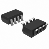
MAX6846KARD3+T Maxim Integrated Products, MAX6846KARD3+T Datasheet - Page 10

MAX6846KARD3+T
Manufacturer Part Number
MAX6846KARD3+T
Description
IC BATTERY MON ADJ SOT23-8
Manufacturer
Maxim Integrated Products
Datasheet
1.MAX6847KAYD7T.pdf
(12 pages)
Specifications of MAX6846KARD3+T
Function
Battery Monitor
Battery Type
Alkaline, Li-Ion, NiCd, NiMH
Voltage - Supply
1 V ~ 5.5 V
Operating Temperature
-40°C ~ 85°C
Mounting Type
Surface Mount
Package / Case
SOT-23-8
Number Of Voltages Monitored
1
Monitored Voltage
1.8 V to 3.3 V
Manual Reset
Not Resettable
Watchdog
No Watchdog
Supply Voltage (max)
5.5 V
Supply Voltage (min)
1.6 V
Maximum Power Dissipation
714 mW
Maximum Operating Temperature
+ 85 C
Mounting Style
SMD/SMT
Minimum Operating Temperature
- 40 C
Lead Free Status / RoHS Status
Lead free / RoHS Compliant
Low-Power, Adjustable Battery Monitors with
Hysteresis and Integrated µP Reset
1) Choose a value for R
2) Calculate R3 based on R
3) Calculate R2 based on R
4) Calculate R1 based on R
5) LBOL high-trip level:
6) LBOH high-trip level:
For monitoring multicell Li+ (or a higher number of alka-
line/NiCd/NiMH cells), connect V
between 1.6V to 5.5V. Figure 6 shows V
directly to V
R3, see the Resistor-Value Selection section.
The MAX6848/MAX6849 dual battery monitors can be
used in conjunction with a DC-DC converter to power
microprocessor systems using a single Li+ cell or two
Figure 6. Monitoring Multicell Li+ Applications
10
Monitoring Multicell Battery Applications
R3. Because the MAX6848/MAX6849 have very high
input impedance, R
upper trip point:
lower trip point:
______________________________________________________________________________________
V
MONITORED
R
R1
R2
R3
2
CC.
R
R
=
1
3
To calculate the values of R1, R2, and
=
DC-DC Converter Application
=
582
V
V
LTHIN
HTHIN
R
TRIPHIGH
TRIPLOW
582
TOTAL
mV
TOTAL
V
V
DD
TRIPLOW
TOTAL
mV
V
TRIPHIGH
×
MAX6846
MAX6847
MAX6848
MAX6849
TOTAL
TOTAL
can be up to 500kΩ.
R
* FOR THE MAX6846/MAX6847.
( ) FOR THE MAX6848/MAX6849.
×
-
V
✕
✕
, the sum of R1, R2, and
CC
TOTAL
R
TOTAL
R
1.05
1.05
2
DD
TOTAL
, R3, and R2:
, R3, and the desired
-
to a supply voltage
(LBOH)
(LBOL)
R
-
LBO*
and the desired
GND
3
R
DD
3
connected
V
CC
to three alkaline/NiCd/NiMH cells. The LBOH output
indicates that the battery voltage is weak, and is used
to warn the microprocessor of potential problems.
Armed with this information, the microprocessor can
reduce system power consumption. The LBOL output
indicates the battery is empty and system power should
be disabled. By connecting LBOL to the SHDN pin of the
DC-DC converter, power to the microprocessor is
removed. Microprocessor power does not return until the
battery has recharged to a voltage greater than V
(see Figure 7).
Table 1. Factory-Trimmed V
Threshold Levels
Table 2. V
Guide
Figure 7. DC-DC Converter Application
PERIOD SUFFIX
3.6V
TIMEOUT
Li+
D3
D7
PART NO.
SUFFIX
( _ )
W
R
CC
T
S
Z
Y
V
Reset Timeout Period Suffix
V
LTHIN
HTHIN
IN
DD
MAX6848
MAX6849
ACTIVE TIMEOUT PERIOD (ms)
DC-DC
SHDN
LBOL
GND
1200
MIN
150
RESET
LBOH
OUT
V
CC
THRESHOLD (V)
V
CC
CC
RESET
NOMINAL
3.075
2.925
2.625
2.313
2.188
1.665
1.575
NMI
RESET
Reset
GND
V
µP
CC
MAX
2400
300
LTH+


