MCP73837-NVI/MF Microchip Technology, MCP73837-NVI/MF Datasheet
MCP73837-NVI/MF
Specifications of MCP73837-NVI/MF


Related parts for MCP73837-NVI/MF


MCP73837-NVI/MF Summary of contents
Page 1
... The MCP73837/8 limits the charge current based on die temperature during high power or high ambient conditions. This thermal regulation optimizes the charge cycle time while maintaining the device reliability ...
Page 2
... Ac-dc Adapter USB Port 4.7 µF 4.7 µF DS22071A-page 2 MCP73837/8 10-Lead MSOP BAT THERM USB STAT1 (TE) STAT2 4 7 PROG2 PROG1 SS MCP73837 Typical Application THERM USB 1 kΩ 3 STAT1 1 kΩ 4 STAT2 PROG2 1 kΩ PROG1 MCP73838 Typical Application THERM USB 1 KΩ 3 STAT1 1 KΩ ...
Page 3
... Functional Block Diagram (MCP73837/8) DIRECTION CONTROL V USB SENSEFET G=0.001 SENSEFET G=0.001 DIRECTION CONTROL V AC SENSEFET G=0.001 SENSEFET G=0.001 PROG1 REFERENCE, V REF (1.21V) BIAS, UVLO, AND SHDN VO UVLO REG TERM PROG2 CHARGE CHARGE CONTROL, STAT1 TIMER, AND STATUS LOGIC STAT2 LDO PG (TE) ...
Page 4
... MCP73837/8 1.0 ELECTRICAL CHARACTERISTICS Absolute Maximum Ratings† V ................................................................................7. All Inputs and Outputs w.r.t. V ............... -0 Maximum Junction Temperature, T ............Internally Limited J Storage temperature .....................................-65°C to +150°C ESD protection on all pins Human Body Model (1 Series with 100 pF) ......≥ Machine Model (200 pF, No Series Resistance) .............300V ...
Page 5
... Automatic Recharge Recharge Voltage Threshold Ratio V Pass Transistor ON-Resistance ON-Resistance Battery Discharge Current Output Reverse Leakage Current Status Indicators - STAT1, STAT2, PG (MCP73837) Sink Current Low Output Voltage Input Leakage Current PROG1 Input (PROG1) Charge Impedance Range Shutdown Impedance PROG2 Inputs (PROG2) ...
Page 6
... MCP73837/8 DC CHARACTERISTICS (Continued) Electrical Specifications: Unless otherwise indicated, all limits apply for -40°C to +85°C. Typical values are at +25° Parameters Timer Enable (TE) Input High Voltage Level Input Low Voltage Level Input Leakage Current Thermistor Bias Thermistor Current Source Thermistor Comparator ...
Page 7
... Min Typ Max T -40 — + -40 — +125 J T -65 — +150 A θ — 113 — JA θ — 41 — JA MCP73837/8 (typical) + 0.3V] to 6V. Units Conditions ms V Low to High < > V BAT PTH BAT PTH ms I Rising to 90 OUT REG ms Average V Rise/Fall BAT ms Average I Falling ...
Page 8
... MCP73837/8 2.0 TYPICAL PERFORMANCE CURVES Note: The graphs and tables provided following this note are a statistical summary based on a limited number of samples and are provided for informational purposes only. The performance characteristics listed herein are not tested or guaranteed. In some graphs or tables, the data presented may be outside the specified operating range (e ...
Page 9
... PROG 1100 V = 5.2V DD 1000 900 800 700 600 500 400 300 200 100 0 ) vs. FIGURE 2-12: OUT Junction Temperature (T MCP73837/8 = +25°C, Constant-voltage mode kΩ PROG V = 5.2V DD Ambient Temperature (°C) Charge Current (I ) vs. OUT ). kΩ PROG V = 5.2V DD Ambient Temperature (°C) Charge Current ( ...
Page 10
... MCP73837/8 Note: Unless otherwise indicated 600 550 500 450 400 350 300 250 200 150 100 50 0 Junction Temperature (°C) FIGURE 2-13: Charge Current (I Junction Temperature ( 120 110 100 Junction Temperature (°C) FIGURE 2-14: Charge Current (I Junction Temperature ( 52.0 51.5 51.0 50 ...
Page 11
... FIGURE 2-23 1A). OUT 0.04 0.02 0 -0.02 -0.04 -0.06 -0.08 -0.1 -0.12 FIGURE 2-24: (USB = Low). MCP73837/8 = +25°C, Constant-voltage mode 100 mA 0.05 OUT 0 -0.05 -0.1 -0.15 -0.2 -0.25 -0.3 Time (Minutes) Load Transient Response. V UVLO Start Delay ...
Page 12
... MCP73837/8 Note: Unless otherwise indicated UVLOVAC FIGURE 2-25: V UVLO Start Delay USB (USB = High) 5.0 4.0 3.0 2 5. Ω PROG 1200 mAh Li-Ion Battery 0.0 Time (Minutes) FIGURE 2-26: Complete Charge Cycle (1200 mAh Li-Ion Battery). 4.5 4.0 3.5 3.0 2 ...
Page 13
... PROG1 to V set point of precondition and termination when the AC- Adapter is present. PROG1 also functions as device charge control enable. The MCP73837/8 is shut down when an impedance value greater than 70 kΩ is applied to PROG1. When PROG1 is floating, the MCP73837/8 enters stand-by mode. ...
Page 14
... USB-Port is present. When PROG2 is floating, the MCP73837/8 enters in stand-by mode. 3.9 Power Good (PG) Power Good (PG) is available only on MCP73837 open-drain logic output for connection to a LED for input power supply indication. Alternatively, a pull- up resistor can be applied for interfacing to a host microcontroller. ...
Page 15
... DEVICE OVERVIEW The MCP73837/8 devices are simple, yet fully integrated linear charge management controllers. operational flow algorithm. SYSTEM TEST (LDO) MODE V > (V -100 mV) THERM DD STAT1 = LOW STAT2 = LOW PG = LOW Timer Suspended TEMPERATURE FAULT No Charge Current STAT1 = Hi-Z STAT2 = Hi LOW Timer Suspended FIGURE 4-1: Flow Chart ...
Page 16
... A charge current programming resistor must be con- nected from PROG1 the PROG1 or PROG2 SS pin are open or floating, the MCP73837/8 is disabled and the battery reverse discharge current is less than 2 µA. In this manner, the PROG1 pin acts as a charge enable and can be used as a manual shutdown. ...
Page 17
... The timer period is factory set and can be disabled. Refer to Section 1.0 “Electrical Characteristics” for charge termination current ratio and timer period options. The charge current is latched off and the MCP73837/8 enters a charge complete mode. 4.8 Automatic Recharge ...
Page 18
... DD 5.1.5 SYSTEM TEST (LDO) MODE The MCP73837/8 can be placed in a system test mode. and V In this mode, the MCP73837/8 operates as a low drop- AC USB out linear regulator (LDO). The output voltage is regulated to the factory set voltage regulation option. The available output current is limited to the pro- grammed fast charge current ...
Page 19
... USB-PORT CURRENT REGULATION SELECT (PROG2) For the MCP73837/8, driving the PROG2 input to a logic Low selects the low charge current setting (maximum 100 mA). Driving the PROG2 input to a logic High selects the high charge current setting (maximum 500 mA). TABLE 5-1: ...
Page 20
... MCP73837/8 6.0 APPLICATIONS The MCP73837/8 devices are designed to operate in conjunction with a host microcontroller or in stand- alone applications. The MCP73837/8 devices provide the preferred charge algorithm for Lithium-Ion and USB Port C IN1 REGULATED C IN2 WALL CUBE FIGURE 6-1: MCP73837 Typical Stand-Alone Application Circuit. ...
Page 21
... Alternatively, the DFN package could be utilized to reduce the charge cycle times. 6.1.1.3 External Capacitors The MCP73837/8 is stable with or without a battery load. In order to maintain good AC stability in the Constant Voltage mode, a minimum capacitance of 1 µF is recommended to bypass the V This capacitance provides compensation when there is no battery load ...
Page 22
... Package Marking Information 10-Lead DFN Part Number * 1 10 XXXX 2 9 MCP73837-FCI/MF XYWW 3 8 MCP73837-FJI/MF NNN 4 7 MCP73837-NVI/ MCP73838-FCI/MF MCP73838-FJI/MF MCP73838-NVI/MF * Consult Factory for Alternative Device Options. 10-Lead MSOP * * Part Number * MCP73837-FCI/UN XXXXXX MCP73837-FJI/UN YWWNNN MCP73837-NVI/UN MCP73838-FCI/UN MCP73838-FJI/UN MCP73838-NVI/UN * Consult Factory for Alternative Device Options. ...
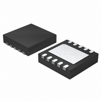
Page 23
... D N NOTE TOP VIEW A3 © 2007 Microchip Technology Inc EXPOSED PAD BOTTOM VIEW A A1 NOTE 2 MCP73837 NOTE DS22071A-page 23 ...
Page 24
... MCP73837 NOTE DS22071A-page φ © 2007 Microchip Technology Inc. ...
Page 25
... APPENDIX A: REVISION HISTORY Revision A (November 2007) • Original Release of this Document. © 2007 Microchip Technology Inc. MCP73837/8 DS22071A-page 25 ...
Page 26
... MCP73837/8 NOTES: DS22071A-page 26 © 2007 Microchip Technology Inc. ...
Page 27
... MCP73837-FCI/UN: 10-lead MSOP pkg. b) MCP73837-FJI/UN: 10-lead MSOP pkg. c) MCP73837-NVI/UN: 10-lead MSOP pkg. d) MCP73837-FCI/MF: 10-lead DFN pkg. e) MCP73837-FJI/MF: 10-lead DFN pkg. f) MCP73837-NVI/MF: 10-lead DFN pkg. a) MCP73838-FCI/UN: 10-lead MSOP pkg. b) MCP73838-FJI/UN: 10-lead MSOP pkg. c) MCP73838-NVI/UN: 10-lead MSOP pkg. d) MCP73838-FCI/MF: 10-lead DFN pkg. e) MCP73838-FJI/MF: 10-lead DFN pkg. ...
Page 28
... MCP73837/8 NOTES: DS22071A-page 28 © 2007 Microchip Technology Inc. ...
Page 29
... PowerInfo, PowerMate, PowerTool, REAL ICE, rfLAB, Select Mode, Smart Serial, SmartTel, Total Endurance, UNI/O, WiperLock and ZENA are trademarks of Microchip Technology Incorporated in the U.S.A. and other countries. SQTP is a service mark of Microchip Technology Incorporated in the U.S.A. All other trademarks mentioned herein are property of their respective companies. ...
Page 30
... Fax: 886-3-572-6459 Taiwan - Kaohsiung Tel: 886-7-536-4818 Fax: 886-7-536-4803 Taiwan - Taipei Tel: 886-2-2500-6610 Fax: 886-2-2508-0102 Thailand - Bangkok Tel: 66-2-694-1351 Fax: 66-2-694-1350 © 2007 Microchip Technology Inc. EUROPE Austria - Wels Tel: 43-7242-2244-39 Fax: 43-7242-2244-393 Denmark - Copenhagen Tel: 45-4450-2828 Fax: 45-4485-2829 France - Paris Tel: 33-1-69-53-63-20 ...