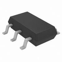
LTC1734LES6-4.2#TRM Linear Technology, LTC1734LES6-4.2#TRM Datasheet - Page 3

LTC1734LES6-4.2#TRM
Manufacturer Part Number
LTC1734LES6-4.2#TRM
Description
IC CHARGER BATT LIN LI-ION SOT23
Manufacturer
Linear Technology
Datasheet
1.LTC1734LES6-4.2TRMPBF.pdf
(12 pages)
Specifications of LTC1734LES6-4.2#TRM
Function
Charge Management
Battery Type
Li-Ion, NiCd, NiMH
Voltage - Supply
4.55 V ~ 8 V
Operating Temperature
-40°C ~ 85°C
Mounting Type
Surface Mount
Package / Case
SOT-23-6 Thin, TSOT-23-6
Lead Free Status / RoHS Status
Contains lead / RoHS non-compliant
Other names
LTC1734LES6-4.2#TRMTR
Available stocks
Company
Part Number
Manufacturer
Quantity
Price
temperature range, otherwise specifications are at T
otherwise noted. All current into a pin is positive and current out of a pin is negative. All voltages are referenced to GND, unless
otherwise specified.
SYMBOL
Charger Manual Control
V
V
I
Protection
I
Note 1: Absolute Maximum Ratings are those values beyond which the life
of a device may be impaired.
Note 2: The LTC1734LE is guaranteed to meet performance specifications
from 0 C to 70 C ambient temperature range and 0 C to 100 C junction
temperature range. Specifications over the – 40 C to 85 C operating
ambient temperature range are assured by design, characterization and
correlation with statistical process controls.
Note 3: Assumes that the external PNP pass transistor has negligible B-C
reverse-leakage current when the collector is biased at 4.2V (V
base is biased at 5V (V
TYPICAL PERFOR A CE CHARACTERISTICS
ELECTRICAL CHARACTERISTICS
PROGPU
DSHRT
MSDT
MSHYS
4.21
4.20
4.19
–50
Float Voltage vs Temperature
and Supply Voltage
I
PNP = FCX589
BAT
–25
PARAMETER
Manual Shutdown Threshold
Manual Shutdown Hysteresis
Program Pin Pull-Up Current
Drive Output Short-Circuit Current Limit
= 10mA
0
V
TEMPERATURE ( C)
CC
= 4.55V
25
CC
).
50
V
CC
= 8V
75
W
100
1734 G01
U
125
4.201
4.200
4.199
A
Float Voltage vs I
0
CONDITIONS
V
V
V
V
= 25 C. V
BAT
V
T
PNP = FCX589
R
PROG
PROG
PROG
DRIVE
A
CC
PROG
= 25 C
) and the
= 5V
25
The
= 2100
Increasing
Decreasing from V
= 2.5V
= V
50
CC
CC
denotes the specifications which apply over the full operating
= 5V, GND = 0V and V
75
I
BAT
Note 4: Assumes that the external PNP pass transistor has negligible B-E
reverse-leakage current when the emitter is biased at 0V (V
base is biased at 4.2V (V
Note 5: The 4.68V maximum undervoltage lockout (UVLO) exit threshold
must first be exceeded before the minimum V
Short duration drops below the minimum V
microseconds or less are ignored by the UVLO. If manual shutdown is
entered, then V
threshold before manual shutdown can be exited. When operating near the
minimum V
must be used.
(mA)
BAT
100
MSDT
125
CC
150
, a suitable PNP transistor with a low saturation voltage
CC
1734 G02
must be higher than the 4.68V maximum UVLO
175
BAT
BAT
is equal to the float voltage unless
).
52
51
50
49
48
–50
I
and Supply Voltage
BAT1
R
PNP = FCX589
PROG
–25
2.05
MIN
vs Temperature
= 7.5k
– 6
35
CC
0
CC
TEMPERATURE ( C)
specification of several
specification applies.
V
2.15
TYP
CC
25
– 3
90
65
LTC1734L
= 4.55V AND 8V
50
MAX
2.25
– 1.5
130
CC
75
) and the
100
UNITS
1734 G03
3
1734lf
mV
mA
125
V
A


