ISL9211IRU68XZ-T Intersil, ISL9211IRU68XZ-T Datasheet - Page 8

ISL9211IRU68XZ-T
Manufacturer Part Number
ISL9211IRU68XZ-T
Description
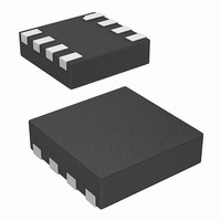
IC SAFETY CIRCUIT CHARGE 8-TDFN
Manufacturer
Intersil
Datasheet
1.ISL9211IRU68XZ-T.pdf
(9 pages)
Specifications of ISL9211IRU68XZ-T
Function
Battery Monitor
Battery Type
Lithium-Ion (Li-Ion)
Voltage - Supply
4.3 V ~ 24 V
Operating Temperature
-40°C ~ 85°C
Mounting Type
Surface Mount
Package / Case
8-µTDFN
Lead Free Status / RoHS Status
Lead free / RoHS Compliant
Other names
ISL9211IRU68XZ-TTR
During the load current step-down transient, the energy
stored in the parasitic inductor is used to charge the input
decoupling capacitor C
the power NFET slowly during the OCP and the battery OVP
event. Because of such design, the input overshoot during
those events is not significant. During an input OVP,
however, the NFET is turned in less than 1µs and can lead to
significant overshoot. Higher capacitance reduces the
overshoot.
The overshoot caused by a hot insertion is not very
dependent on the decoupling capacitance value. Especially
Intersil products are sold by description only. Intersil Corporation reserves the right to make changes in circuit design, software and/or specifications at any time without
notice. Accordingly, the reader is cautioned to verify that data sheets are current before placing orders. Information furnished by Intersil is believed to be accurate and
reliable. However, no responsibility is assumed by Intersil or its subsidiaries for its use; nor for any infringements of patents or other rights of third parties which may result
from its use. No license is granted by implication or otherwise under any patent or patent rights of Intersil or its subsidiaries.
FIGURE 16. EQUIVALENT CIRCUIT FOR THE ISL9211 INPUT
AC/DC
ADAPTER
C1
All Intersil U.S. products are manufactured, assembled and tested utilizing ISO9000 quality systems.
Intersil Corporation’s quality certifications can be viewed at www.intersil.com/design/quality
L
2
For information regarding Intersil Corporation and its products, see www.intersil.com
CABLE
. The ISL9211 is designed to turn off
8
R
C2
HANDHELD SYSTEM
ISL9211
ISL9211
when ceramic type capacitors are used for decoupling. In
theory, the over-shoot can rise up to twice of the DC output
voltage of the AC adapter. The actual peak voltage is
dependent on the damping factor that is mainly determined
by the parasitic resistance (R in Figure 16).
In practice, the input decoupling capacitor is recommended
to use a 25V, X5R dielectric ceramic capacitor with a value
between 0.1µF to 1µF.
The output of the ISL9211 and the input of the charging
circuit typically share one decoupling capacitor. The
selection of that capacitor is mainly determined by the
requirement of the charging circuit. When using the ISL6292
family chargers, a 1µF, 6.3V, X5R capacitor is
recommended.
Layout Recommendation
The ISL9211 uses a 2x2 DFN package. Use some copper on
the component layer if possible to improve the thermal
performance if possible.
January 13, 2009
FN6658.4


