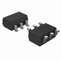
MCP73826-4.2VCHTR Microchip Technology, MCP73826-4.2VCHTR Datasheet - Page 8

MCP73826-4.2VCHTR
Manufacturer Part Number
MCP73826-4.2VCHTR
Description
IC CONTROLLR LI-ION 4.2V SOT23-6
Manufacturer
Microchip Technology
Datasheet
1.MCP73826-4.2VCHTR.pdf
(24 pages)
Specifications of MCP73826-4.2VCHTR
Battery Type
Lithium-Ion (Li-Ion)
Function
Charge Management
Voltage - Supply
4.5 V ~ 5.5 V
Operating Temperature
-20°C ~ 85°C
Mounting Type
Surface Mount
Package / Case
SOT-23-6
Input Voltage
5.5V
Battery Charge Voltage
4.2V
Battery Ic Case Style
SOT-23
No. Of Pins
6
No. Of Series Cells
1
Operating Temperature Range
-20°C To +85°C
Svhc
No SVHC
Output Voltage
4.242 V
Operating Supply Voltage
4.5 V to 5.5 V
Supply Current
560 mA
Maximum Operating Temperature
+ 85 C
Minimum Operating Temperature
- 20 C
Mounting Style
SMD/SMT
Lead Free Status / RoHS Status
Lead free / RoHS Compliant
Lead Free Status / RoHS Status
Lead free / RoHS Compliant, Lead free / RoHS Compliant
Other names
MCP738264.2VCHTR
Available stocks
Company
Part Number
Manufacturer
Quantity
Price
Part Number:
MCP73826-4.2VCHTR
Manufacturer:
MICROCHIP/微芯
Quantity:
20 000
MCP73826
3.0
The descriptions of the pins are listed in Table 3-1.
TABLE 3-1:
3.1
Input to force charge termination, initiate charge, or ini-
tiate recharge.
3.2
Connect to negative terminal of battery.
3.3
Voltage sense input. Connect to positive terminal of
battery. Bypass to GND with a minimum of 10 µF to
ensure loop stability when the battery is disconnected.
A precision internal resistor divider regulates the final
voltage on this pin to V
DS21705A-page 8
Pin
1
2
3
4
5
6
PIN DESCRIPTION
Logic Shutdown (SHDN)
Battery Management 0V Reference
(GND)
Cell Voltage Monitor Input (V
SHDN
Name
V
V
GND
V
V
DRV
SNS
BAT
IN
Pin Function Table.
Logic Shutdown
Battery Management
0V Reference
Cell Voltage Monitor Input
Drive Output
Battery Management
Input Supply
Charge Current Sense Input
REG
.
Description
BAT
)
3.4
Direct output drive of an external P-channel MOSFET
pass transistor for current and voltage regulation.
3.5
A supply voltage of 4.5V to 5.5V is recommended.
Bypass to GND with a minimum of 10 µF.
3.6
Charge current is sensed via the voltage developed
across an external precision sense resistor. The sense
resistor must be placed between the supply voltage
(V
50 m
1 A, typically.
IN
) and the source of the external pass transistor. A
sense resistor produces a fast charge current of
Drive Output (V
Battery Management Input Supply
(V
Charge Current Sense Input (V
IN
)
2002 Microchip Technology Inc.
DRV
)
SNS
)


