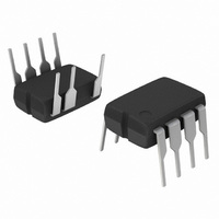
NCP1013AP100G ON Semiconductor, NCP1013AP100G Datasheet - Page 9

NCP1013AP100G
Manufacturer Part Number
NCP1013AP100G
Description
IC OFFLINE SWIT SMPS CM OVP 8DIP
Manufacturer
ON Semiconductor
Datasheet
1.NCP1010ST100T3G.pdf
(24 pages)
Specifications of NCP1013AP100G
Output Isolation
Isolated
Frequency Range
90 ~ 110kHz
Voltage - Input
8.5 ~ 10 V
Voltage - Output
700V
Power (watts)
19W
Operating Temperature
-40°C ~ 125°C
Package / Case
8-DIP (0.300", 7.62mm), 7 Leads
Duty Cycle (max)
72 %
Mounting Style
Through Hole
Switching Frequency
110 KHz
Operating Supply Voltage
- 0.3 V to + 10 V
Maximum Operating Temperature
+ 150 C
Synchronous Pin
No
Topology
Flyback
Lead Free Status / RoHS Status
Lead free / RoHS Compliant
Other names
NCP1013AP100GOS
Available stocks
Company
Part Number
Manufacturer
Quantity
Price
Company:
Part Number:
NCP1013AP100G
Manufacturer:
ON Semiconductor
Quantity:
9 100
Part Number:
NCP1013AP100G
Manufacturer:
ON/安森美
Quantity:
20 000
through the various timing events as portrayed by Figure 16.
the V
detects that V
internal current source to bring V
again: a cycle takes place whose low frequency depends on
the V
takes place on the V
(VCC
operation of the DSS.
offer an adequate startup time, i.e. ensure regulation is
reached before V
the fault condition mode). If we know that ΔV = 1.0 V
and ICC1 (max) is 1.1 mA (for instance we selected an 11 Ω
device switching at 65 kHz), then the V
be calculated using:
suppose that the SMPS needs 10 ms to startup, then we will
calculate C to offer a 15 ms period. As a result, C should be
greater than 20 mF thus the selection of a 33 mF/16 V
capacitor is appropriate.
Short Circuit Protection
arrangement that permanently monitors the assertion of an
internal error flag. This error flag is, in fact, a signal that
instructs the controller that the internal maximum peak
current limit is reached. This naturally occurs during the
startup period (Vout is not stabilized to the target value) or
when the optocoupler LED is no longer biased, e.g. in a
short- -circuit condition or when the feedback network is
broken. When the DSS normally operates, the logic checks
The protection burst duty- -cycle can easily be computed
Being loaded by the circuit consumption, the voltage on
As one can see, the V
The internal protection circuitry involves a patented
CC
CC
OFF
capacitor and the IC consumption. A 1.0 V ripple
capacitor goes down. When the DSS controller
+ VCC
CC
has reached 7.5 V (VCC
CC
ON
crosses 7.5 V (otherwise the part enters
CC
)/2. Figure 14 portrays a typical
CC
C ≥
8.00
6.00
4.00
2.00
pin whose average value equals
Figure 14. The Charge/Discharge Cycle Over a 10 mF V
capacitor shall be dimensioned to
0
ICC1 · tstartup
CC
ΔV
Startup Period
toward 8.5 V and stops
Vcc
Device
Internally
Pulses
ON
CC
), it activates the
capacitor can
(eq. 1)
8.5 V
. Let’s
http://onsemi.com
9
7.5 V
for the presence of the error flag every time V
VCC
the IC works normally. If the error signal is active, then the
NCP101X immediately stops the output pulses, reduces its
internal current consumption and does not allow the startup
source to activate: V
the so- -called latch- -off level, where the current source
activates again to attempt a new restart. When the error is
gone, the IC automatically resumes its operation. If the
default is still there, the IC pulses during 8.5 V down to 7.5 V
and enters a new latch- -off phase. The resulting burst
operation guarantees a low average power dissipation and
lets the SMPS sustain a permanent short- -circuit. Figure 15
shows the corresponding diagram.
FB
4 V
ON
Figure 15. Simplified NCP101X Short- -Circuit
. If the error flag is low (peak limit not active) then
Division
Active?
Clamp
Max
Ip
CC
Detection Circuitry
CC
Capacitor
drops toward ground until it reaches
Current Sense
V
Information
CC
Flag
VCC
Signal
ON
+
--
CC
crosses
Reset
Latch
To


