VIPER27LN STMicroelectronics, VIPER27LN Datasheet - Page 4
VIPER27LN
Manufacturer Part Number
VIPER27LN
Description
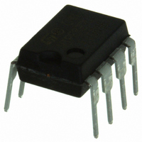
IC OFFLINE CONV PWM OVP 8DIP
Manufacturer
STMicroelectronics
Series
VIPer™ plusr
Specifications of VIPER27LN
Output Isolation
Isolated
Frequency Range
54 ~ 66kHz
Voltage - Input
8.5 ~ 23.5 V
Voltage - Output
800V
Power (watts)
24W
Operating Temperature
-40°C ~ 150°C
Package / Case
8-DIP (0.300", 7.62mm), 7 Leads
Output Voltage
800 V
Output Power
1 W
Input Voltage
- 0.3 V
Switching Frequency
115 KHz
Operating Temperature Range
- 40 C to + 150 C
Mounting Style
Through Hole
Duty Cycle (max)
80 %
Number Of Outputs
1
For Use With
497-9084 - EVAL BOARD FOR VIPER27LX
Lead Free Status / RoHS Status
Lead free / RoHS Compliant
Other names
497-8390-5
Available stocks
Company
Part Number
Manufacturer
Quantity
Price

Part Number:
VIPER27LN
Manufacturer:
ST
Quantity:
20 000


Pin settings
3
Note:
4/31
Pin settings
Figure 3.
The copper area for heat dissipation has to be designed under the DRAIN pins.
Table 3.
DIP7
7,8
1
2
3
4
5
-
Pin n.
SO16N
13...16 DRAIN
1...2
4
5
6
7
8
Connection diagram (top view)
Pin description
CONT
Name
GND
VDD
N.A.
BR
FB
This pin represents the device ground and the source of the power
section.
Not available for user. It can be connected to GND (pins 1-2) or left not
connected.
Supply voltage of the control section. This pin also provides the charging
current of the external capacitor during start-up time.
Control pin. The following functions can be selected:
1. current limit set point adjustment. The internal set default value of the
cycle-by-cycle current limit can be reduced by connecting to ground an
external resistor.
2. output voltage monitoring. A voltage exceeding V
Table 8 on page 7
This function is strobed and digitally filtered for high noise immunity.
Control input for duty cycle control. Internal current generator provides
bias current for loop regulation. A voltage below the threshold V
activates the burst-mode operation. A level close to the threshold V
means that we are approaching the cycle-by-cycle over-current set point.
Brownout protection input with hysteresis. A voltage below the threshold
V
consumption. Device operation restarts as the voltage exceeds the
threshold V
High voltage drain pin. The built-in high voltage switched start-up bias
current is drawn from this pin too.
Pins connected to the metal frame to facilitate heat dissipation.
BRth
shuts down (not latch) the device and lowers the power
Doc ID 15133 Rev 5
BRth
+ V
) shuts the IC down reducing the device consumption.
BRhyst
. It can be connected to ground when not used.
Function
OVP
threshold (see
FBbm
VIPER27
FBlin
Related parts for VIPER27LN
Image
Part Number
Description
Manufacturer
Datasheet
Request
R

Part Number:
Description:
IC OFFLINE CONV PWM OVP OCP 8DIP
Manufacturer:
STMicroelectronics
Datasheet:

Part Number:
Description:
IC OFFLINE SWIT PWM SMPS CM 8DIP
Manufacturer:
STMicroelectronics
Datasheet:
Part Number:
Description:
IC OFFLINE SWIT PWM SMPS 8DIP
Manufacturer:
STMicroelectronics
Datasheet:
Part Number:
Description:
IC OFFLINE SWIT PWM CM OTP 8DIP
Manufacturer:
STMicroelectronics
Datasheet:

Part Number:
Description:
IC SWIT PWM SMPS CM PENTAWATT5
Manufacturer:
STMicroelectronics
Datasheet:

Part Number:
Description:
IC SWIT PWM SMPS CM PENTAWATT5
Manufacturer:
STMicroelectronics
Datasheet:

Part Number:
Description:
IC OFFLINE SWIT PWM SMPS 8SOIC
Manufacturer:
STMicroelectronics
Datasheet:

Part Number:
Description:
IC OFFLINE SWIT PWM POWERSO10
Manufacturer:
STMicroelectronics
Datasheet:

Part Number:
Description:
IC OFFLINE CONV PWM OVP OCP 7DIP
Manufacturer:
STMicroelectronics
Datasheet:

Part Number:
Description:
IC OFFLINE CONV PWM OVP 8DIP
Manufacturer:
STMicroelectronics
Datasheet:
Part Number:
Description:
IC SWIT SMPS CM OTP PENTAWATT5
Manufacturer:
STMicroelectronics
Datasheet:
Part Number:
Description:
IC SWIT PWM SMPS CM PENTAWATT5
Manufacturer:
STMicroelectronics
Datasheet:

Part Number:
Description:
IC OFFLINE CONV PWM OTP 16-SOIC
Manufacturer:
STMicroelectronics
Datasheet:
Part Number:
Description:
IC OFFLINE CONV PWM OTP 16-SOIC
Manufacturer:
STMicroelectronics
Datasheet:
Part Number:
Description:
IC OFFLINE SWIT PWM SMPS 8SOIC
Manufacturer:
STMicroelectronics
Datasheet: