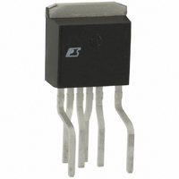
PKS606FN Power Integrations, PKS606FN Datasheet - Page 8

PKS606FN
Manufacturer Part Number
PKS606FN
Description
IC OFFLINE SWIT OTP OCP HV TO262
Manufacturer
Power Integrations
Series
PeakSwitch®r
Specifications of PKS606FN
Mfg Application Notes
PeakSwitch Design Guide AppNote
Output Isolation
Isolated
Frequency Range
250 ~ 304kHz
Voltage - Output
700V
Power (watts)
117W
Operating Temperature
-40°C ~ 150°C
Package / Case
TO-262-7 (Formed Leads), 5 Leads
Output Voltage
12 V
Input / Supply Voltage (max)
265 VAC
Input / Supply Voltage (min)
85 VAC
Duty Cycle (max)
65 %
Switching Frequency
47 KHz
Supply Current
25 uA
Operating Temperature Range
- 40 C to + 150 C
Mounting Style
Through Hole
For Use With
596-1198 - KIT REF DESIGN 36-72W MOTOR DRVR
Lead Free Status / RoHS Status
Lead free / RoHS Compliant
Other names
596-1125-5
Available stocks
Company
Part Number
Manufacturer
Quantity
Price
Company:
Part Number:
PKS606FN
Manufacturer:
power
Quantity:
15 000
Part Number:
PKS606FN
Manufacturer:
POWER
Quantity:
20 000
Step 5 – Choose Core and Bobbin Based on Output
Power, and Enter A
Core effective cross-sectional area, A
Core effective path length, L
Core ungapped effective inductance, A
Bobbin width, BW: (mm)
Tape margin width equal to half the total margin, M (mm)
Primary Layers, L
Secondary Turns, N
Figure 11. Transformer Variables Section of Design Spreadsheet.
Core Type
By default if the core type cell is left empty, the spreadsheet
will select the smallest commonly available core suitable for the
continuous output power. Available cores can be selected from
the drop down list in the tool bar of the PI Xls design software.
The grey override cells can be used to enter the core and bobbin
parameter directly by a user. This is useful if the user wants to
use a core that is not on the list, or the specific core or bobbin
information differs from that recalled by the spreadsheet.
Safety Margin, M (mm)
For designs that require isolation but are not using triple
insulated wire, the width of the safety margin to be used on
each side of the bobbin should be entered here. For universal
input designs, a total margin of 6.2 mm would be required, and
a value of 3.1 mm would be entered into the spreadsheet. For
vertical bobbins, the margin may not be symmetrical. However
if a total margin of 6.2 mm were required, then 3.1 mm would
still be entered even if the physical margin is only on one side
of the bobbin.
For designs using triple insulated wire, it may still be necessary
to enter a small margin in order to meet the required safety
creepage distances. Many bobbins exist for each core size,
and each will have different mechanical spacing. Refer to the
specific bobbin data sheet or seek guidance from your safety
expert or transformer vendor to determine what specific margin
is required.
Since margin construction reduces the available area for the
windings, it may not be suitable for small core sizes. If after
entering the margin, more than three primary layers (L) are
Rev. E 02/07
ENTER TRANSFORMER CORE/CONSTRUCTION VARIABLES
Core Type
Core
Bobbin
AE
LE
AL
BW
M
L
NS
8
AN-41
S
E
, L
E
, A
E
: (cm).
L
, BW, M, L, N
Auto
E
: (cm
L
: (nH/turn
2
EE13_BOBBIN
)
S
2
).
EE13
EE13
0.171 cm^2
1130 nH/T^2
3.02 cm
7.90 mm
0.00 mm
16
3
P/N:
P/N:
required, either a larger core should be selected, or consider a
zero margin design using triple insulated wire.
Primary Layers, L
By default, if the override cell is empty, a value of 3 is assumed.
Primary layers should be in the range of 1 < L < 3 and in general
it should be the lowest number that meets the primary current
density limit of 100 Cmils/Amp (CMA). More than three
layers are possible, but the increased leakage inductance and
physical fit of the windings should be considered. Due to the
high switching frequency of PeakSwitch designs, it is important
to minimize transformer leakage inductance. Therefore
split primary construction is recommended for all designs
regardless of power level. In split primary construction,
half of the primary winding is placed on either side of the
secondary and bias windings, in a sandwich arrangement.
Secondary Turns, N
By default, if the grey override cell is left blank, the minimum
number of secondary turns is calculated such that the maximum
operating flux density B
maximum of 3000 Gauss (300 mT). In general it is not necessary
to enter a number in the override cell except in designs where
a lower operating flux density is desired (see the explanation
of B
Step 6 – Iterate Transformer Design and Generate
Initial Design
Iterate the design making sure that no warnings are displayed.
Any parameters outside the recommended range of values can
be corrected by following the guidance given in the right hand
column.
Once all warnings have been cleared, the output transformer
design parameters can be used to either wind a prototype
transformer or sent to a vendor for samples.
The key transformer electrical parameters are:
Primary Inductance, L
This is the target nominal primary inductance of the
transformer.
M
limits).
Transformer Core (Verify acceptable thermal rise under
continuous load conditions)
PC40EE13-Z
EE13_BOBBIN
Core Effective Cross Sectional Area
Core Effective Path Length
Ungapped Core Effective Inductance
Bobbin Physical Winding Width
Safety Margin Width (Half the Primary to Secondary Creepage
Distance)
Number of Primary Layers
Number of Secondary Turns
S
P
M
(µH)
is kept below the recommended


