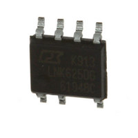
LNK625DG Power Integrations, LNK625DG Datasheet - Page 17

LNK625DG
Manufacturer Part Number
LNK625DG
Description
IC OFFLINE SWIT OTP OCP CV 8SOP
Manufacturer
Power Integrations
Series
LinkSwitch®-CVr
Datasheet
1.LNK625DG.pdf
(18 pages)
Specifications of LNK625DG
Output Isolation
Isolated
Frequency Range
93 ~ 106kHz
Voltage - Output
700V
Power (watts)
13.5W
Operating Temperature
-40°C ~ 150°C
Package / Case
8-SOIC (0.154", 3.90mm Width) 7 leads
Duty Cycle (max)
54 %
Operating Temperature Range
- 40 C to + 150 C
Mounting Style
SMD/SMT
Maximum Operating Temperature
+ 150 C
Minimum Operating Temperature
- 40 C
Number Of Outputs
3
Output Power
8 W
Lead Free Status / RoHS Status
Lead free / RoHS Compliant
Other names
596-1253-5
Available stocks
Company
Part Number
Manufacturer
Quantity
Price
Company:
Part Number:
LNK625DG
Manufacturer:
POWER
Quantity:
15 000
Part Number:
LNK625DG
Manufacturer:
POWER
Quantity:
20 000
Company:
Part Number:
LNK625DG-TL
Manufacturer:
POWER
Quantity:
15 000
Company:
Part Number:
LNK625DG-TL
Manufacturer:
PowerInt
Quantity:
7 160
Part Number:
LNK625DG-TL
Manufacturer:
POWER
Quantity:
20 000
Part Ordering Information
www.powerint.com
D07C
2X
0.10 (0.004)
0.25 (0.010)
0.10 (0.004) C
1.35 (0.053)
1.75 (0.069)
Reference
Solder Pad
Dimensions
1.27 (0.050) BSC
2
LNK 625
3.90 (0.154) BSC
1.27 (0.050)
Pin 1 ID
D
2.00 (0.079)
4
D G - TL
B
(0.049 - 0.065)
1.25 - 1.65
1
+
8
4.90 (0.193) BSC
A
+
2
• LinkSwitch Product Family
• CV Series Number
• Package Identifi er
• Package Material
• Tape & Reel and Other Options
Blank
4
5
TL
4.90 (0.193)
P
D
4
G
+
+
6.00 (0.236) BSC
Plastic DIP
Plastic SO-8
GREEN: Halogen Free and RoHS Compliant
Standard Confi gurations
Tape & Reel, 2.5 k pcs for D Package. Not available for P Package.
0.10 (0.004) C
7X 0.31 - 0.51 (0.012 - 0.020)
0.60 (0.024)
7X
D
C
0.25 (0.010) M C A-B D
2X
SEATING PLANE
0.10 (0.004) C
SO-8C
0.20 (0.008) C
A-B
Notes:
1. JEDEC reference: MS-012.
2. Package outline exclusive of mold flash and metal burr.
3. Package outline inclusive of plating thickness.
4. Datums A and B to be determined at datum plane H.
5. Controlling dimensions are in millimeters. Inch dimensions
2X
are shown in parenthesis. Angles in degrees.
SEATING
PLANE
1.04 (0.041) REF
C
H
0.40 (0.016)
1.27 (0.050)
0.17 (0.007)
0.25 (0.010)
LNK623-626
DETAIL A
0 - 8
0.25 (0.010)
BSC
o
DETAIL A
PI-4526-040207
GAUGE
PLANE
Rev. E 09/09
17


