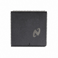
DP8422AV-20 National Semiconductor, DP8422AV-20 Datasheet - Page 8

DP8422AV-20
Manufacturer Part Number
DP8422AV-20
Description
IC CTRLR/DVR CMOS PROGRAM 84PLCC
Manufacturer
National Semiconductor
Datasheet
1.DP8420AV-25.pdf
(58 pages)
Specifications of DP8422AV-20
Controller Type
Dynamic RAM (DRAM)
Voltage - Supply
4.5 V ~ 5.5 V
Operating Temperature
0°C ~ 70°C
Package / Case
84-PLCC
Lead Free Status / RoHS Status
Contains lead / RoHS non-compliant
Other names
*DP8422AV-20
Available stocks
Company
Part Number
Manufacturer
Quantity
Price
Company:
Part Number:
DP8422AV-20
Manufacturer:
Texas Instruments
Quantity:
10 000
3 0 Programming and Resetting
Due to the variety in power supplies power-up times the
internal power up reset circuit may not work in every design
therefore an EXTERNAL RESET must be performed before
the DRAM controller can be programmed and used
After
DP8420A 21A 22A can be programmed by either of two
methods Mode Load Only Programming or Chip Select Ac-
cess Programming After programming the DRC for the first
time after reset the chip enters a 60 ms initialization period
during this period the controller performs refreshes every
13
unnecessary After this stage the chip can be repro-
grammed as many times as the user wishes and the 60 ms
period will not be entered into unless the chip is reset and
programmed again
During the 60 ms initialization period RFIP is asserted low
and RAS toggles every 13
programming bit for refresh (C3) CAS will be inactive (logic
1) and the ‘‘Q’’ outputs will count from 0 to 2047 refreshing
the entire DRAM array The actual initialization time period
is given by the following formula T
Select) (Refresh Clock Fine Tune) (DELCLK Frq )
s or 15
going
s this makes further DRAM warm up cycles
through
the
s or 15
reset
e
4096 (Clock Divisor
s depending on the
FIGURE 5a Chip Reset but Not Programmed
FIGURE 5b Chip Reset and Programmed
procedure
the
8
3 1 EXTERNAL RESET
At power up if the internal power up reset worked all inter-
nal latches and flip-flops are cleared and the part is ready to
be programmed The power up state can also be achieved
by performing an External Reset which is required to insure
proper operation External Reset is achieved by asserting
ML and DISRFSH for at least 16 positive clock edges In
order to perform simply a Reset the ML signal must be
negated before DISRFSH is negated as shown in Figure 5a
This procedure will only reset the controller which now is
ready for programming
While performing an External Reset if the user negates
DISRFSH at least one clock period before negating ML as
shown in Figure 5b
DP8420A 21A 22A with the values in R0– 9 C0– 9 B0 – 1
and ECAS0 The 60 ms initialization period will be entered
since it is the first programming after reset This is a good
way of resetting and programming the part at the same time
Make sure the right programming bits are on the address
lines before ML is negated
The DRC may be Reset and programmed any time on the
fly but the user must make sure that No Access or Refresh
is in progress
ML negated will program the
TL F 8588 – E2
TL F 8588 – E1


