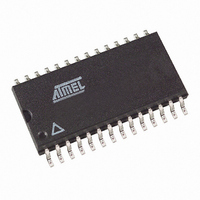
AT27C256R-70RU Atmel, AT27C256R-70RU Datasheet - Page 4

AT27C256R-70RU
Manufacturer Part Number
AT27C256R-70RU
Description
IC OTP 256KBIT 70NS 28SOIC
Manufacturer
Atmel
Datasheet
1.AT27C256R-45PU.pdf
(15 pages)
Specifications of AT27C256R-70RU
Format - Memory
EPROMs
Memory Type
OTP EPROM
Memory Size
256K (32K x 8)
Speed
70ns
Interface
Parallel
Voltage - Supply
4.5 V ~ 5.5 V
Operating Temperature
-40°C ~ 85°C
Package / Case
28-SOIC (8.69mm width)
Density
256Kb
Organization
32Kx8
Interface Type
Parallel
Bus Type
Parallel
In System Programmable
External
Access Time (max)
70ns
Package Type
SOIC
Reprogramming Technique
OTP
Operating Supply Voltage (typ)
5V
Operating Supply Voltage (min)
4.5V
Operating Supply Voltage (max)
5.5V
Supply Current
20mA
Pin Count
28
Mounting
Surface Mount
Operating Temp Range
-40C to 85C
Operating Temperature Classification
Industrial
Lead Free Status / RoHS Status
Lead free / RoHS Compliant
Available stocks
Company
Part Number
Manufacturer
Quantity
Price
Company:
Part Number:
AT27C256R-70RU
Manufacturer:
TI
Quantity:
1 001
Company:
Part Number:
AT27C256R-70RU
Manufacturer:
ATMEL
Quantity:
122
Part Number:
AT27C256R-70RU
Manufacturer:
ATMEL/爱特梅尔
Quantity:
20 000
6. Operating Modes
Notes:
7. DC and AC Operating Conditions for Read Operation
8. DC and Operating Characteristics for Read Operation
Notes:
4
Mode/Pin
Read
Output Disable
Standby
Rapid Program
PGM Verify
Optional PGM Verify
PGM Inhibit
Product Identification
Operating Temp. (Case)
V
Symbol
I
I
I
I
I
V
V
V
V
LI
LO
PP1
SB
CC
OL
OH
CC
IL
IH
(2)
Supply
1. X can be V
2. Refer to Programming Characteristics.
3. V
4. Two identifier bytes may be selected. All Ai inputs are held low (V
1. V
2. V
AT27C256R
low (V
(2)
(2)
H
CC
PP
Parameter
Input Load Current
Output Leakage Current
V
V
V
Input Low Voltage
Input High Voltage
Output Low Voltage
Output High Voltage
= 12.0 ± 0.5V.
(2)
PP
CC
CC
may be connected directly to V
must be applied simultaneously with or before V
(1)
IL
(1)
Active Current
) to select the Manufacturer’s Identification byte and high (V
Read/Standby Current
Standby Current
(2)
(4)
IL
or V
IH
.
CE
V
V
V
V
V
V
V
X
IH
IH
IL
IL
IL
IL
IL
(1)
Ind.
Auto.
Condition
V
V
V
I
I
f = 5 MHz, I
I
I
SB1
SB2
OL
OH
CC
IN
OUT
PP
, except during programming. The supply current would then be the sum of I
= 2.1 mA
= 0V to V
= -400 µA
= V
(CMOS), CE = V
(TTL), CE = 2.0 to V
= 0V to V
CC
OUT
OE
V
V
V
CC
V
V
V
V
X
IH
IH
IH
IL
IL
IL
IL
CC
(1)
= 0 mA, E = V
PP
, and removed simultaneously with or after V
CC
± 0.3V
CC
-40° C - 85° C
+ 0.5V
A0 = V
A1 - A14 = V
5V ± 10%
Ind.
Auto.
Auto.
IL
Ind.
A9 = V
IL
-45
), except A9 which is set to V
IH
X
Ai
Ai
Ai
Ai
Ai
) to select the Device Code byte.
X
X
IH
(1)
(1)
(1)
or V
H
(3)
IL
IL
AT27C256R
Min
-0.6
2.0
2.4
V
V
V
V
V
V
V
V
V
PP
CC
CC
CC
PP
PP
CC
PP
CC
H
V
and A0 which is toggled
-40° C - 125° C
CC
-40° C - 85° C
Max
PP
±10
100
0.8
0.4
±1
±5
±5
10
20
5V ± 10%
1
+ 0.5
..
Identification Code
-70
0014M–EPROM–12/07
Outputs
High Z
High Z
High Z
D
D
D
D
OUT
OUT
OUT
IN
Units
CC
mA
mA
µA
µA
µA
µA
µA
µA
V
V
V
V
and I
PP
.


