CAT24AA01TDI-GT3 ON Semiconductor, CAT24AA01TDI-GT3 Datasheet
CAT24AA01TDI-GT3
Specifications of CAT24AA01TDI-GT3
Available stocks


Related parts for CAT24AA01TDI-GT3

CAT24AA01TDI-GT3 Summary of contents
Page 1
... Supports Standard and Fast I C Protocol • 1 5.5 V Supply Voltage Range • 16−Byte Page Write Buffer • Hardware Write Protection for Entire Memory • Schmitt Triggers and Noise Suppression Filters on I (SCL and SDA) • Low Power CMOS Technology • 1,000,000 Program/Erase Cycles • ...
Page 2
Table 1. ABSOLUTE MAXIMUM RATINGS Parameters Storage Temperature Voltage on any Pin with Respect to Ground (Note 1) Stresses exceeding Maximum Ratings may damage the device. Maximum Ratings are stress ratings only. Functional operation above the Recommended Operating Conditions is ...
Page 3
Table 5. A.C. CHARACTERISTICS Symbol F Clock Frequency SCL t START Condition Hold Time HD:STA t Low Period of SCL Clock LOW t High Period of SCL Clock HIGH t START Condition Setup Time SU:STA t Data In Hold Time ...
Page 4
Power−On Reset (POR) Each CAT24AA01/02 incorporates Power−On Reset (POR) circuitry which protects the internal logic against powering up in the wrong state. The device will power up into Standby mode after V exceeds the POR trigger level CC and will ...
Page 5
... Slave, the Master simply repeats the request until the Slave responds with ACK. Hardware Write Protection With the WP pin held HIGH, the entire memory is protected against Write operations. If the WP pin is left floating or is grounded, it has no impact on the Write operation ...
Page 6
S BUS ACTIVITY ADDRESS R MASTER T S SLAVE SCL 8 th Bit SDA Byte n S BUS ACTIVITY: T SLAVE ADDRESS A R ADDRESS MASTER SLAVE v15 ADDRESS ...
Page 7
... Master responds with NoACK followed by STOP (Figure 12). During Sequential Read the internal byte address is automatically incremented up to the end of memory, where it then wraps around to the beginning of memory. For the CAT24AA01, the internal address counter will not wrap around at the end of the 128 byte memory space ...
Page 8
PIN # 1 IDENTIFICATION TOP VIEW SIDE VIEW Notes: (1) All dimensions are in millimeters. Angles in degrees. (2) Complies with JEDEC MS-012. PACKAGE DIMENSIONS SOIC 8, 150 mils CASE 751BD−01 ISSUE O SYMBOL ...
Page 9
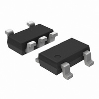
TOP VIEW SIDE VIEW Notes: (1) All dimensions are in millimeters. Angles in degrees. (2) Complies with JEDEC MO-193. PACKAGE DIMENSIONS TSOT−23, 5 LEAD CASE 419AE−01 ISSUE O SYMBOL MIN A A1 0.01 A2 ...
Page 10
... The device used in the above example is a CAT24AA02TDI−GT3 (TSOT−23 5−Lead, Industrial Temperature, NiPdAu, Tape & Reel, 3,000/Reel). 11. For additional package and temperature options, please contact your nearest ON Semiconductor sales office. 12. For information on tape and reel specifications, including part orientation and tape sizes, please refer to our Tape and Reel Packaging Specification Brochure, BRD8011/D ...