STK16C88-WF45 Cypress Semiconductor Corp, STK16C88-WF45 Datasheet - Page 8
STK16C88-WF45
Manufacturer Part Number
STK16C88-WF45
Description
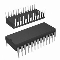
IC NVSRAM 256KBIT 45NS 28DIP
Manufacturer
Cypress Semiconductor Corp
Series
-r
Datasheet
1.STK16C88-WF45.pdf
(15 pages)
Specifications of STK16C88-WF45
Memory Size
256K (32K x 8)
Package / Case
28-DIP (0.600", 15.24mm)
Format - Memory
RAM
Memory Type
NVSRAM (Non-Volatile SRAM)
Speed
45ns
Interface
Parallel
Voltage - Supply
4.5 V ~ 5.5 V
Operating Temperature
0°C ~ 70°C
Data Bus Width
8 bit
Organization
32 K x 8
Interface Type
Parallel
Access Time
45 ns
Supply Voltage (max)
5.5 V
Supply Voltage (min)
4.5 V
Operating Current
70 mA
Maximum Operating Temperature
+ 70 C
Minimum Operating Temperature
0 C
Mounting Style
Through Hole
Memory Configuration
32K X 8
Supply Voltage Range
4.5V To 5.5V
Memory Case Style
DIP
No. Of Pins
28
Operating Temperature Range
0°C To +70°C
Rohs Compliant
Yes
Lead Free Status / RoHS Status
Contains lead / RoHS non-compliant
Lead Free Status / RoHS Status
Lead free / RoHS Compliant, Contains lead / RoHS non-compliant
Available stocks
Company
Part Number
Manufacturer
Quantity
Price
Company:

Part Number:
STK16C88-WF45
Manufacturer:
PANASONIC
Quantity:
34 000
Company:
Part Number:
STK16C88-WF45I
Manufacturer:
IR
Quantity:
12 000


Capacitance
In the following table, the capacitance parameters are listed.
Thermal Resistance
In the following table, the thermal resistance parameters are listed.
AC Test Conditions
Input Pulse Levels .................................................. 0 V to 3 V
Input Rise and Fall Times (10% - 90%)........................ <5 ns
Input and Output Timing Reference Levels ................... 1.5 V
Document Number: 001-50595 Rev. *B
Note
C
C
4. These parameters are guaranteed by design and are not tested.
IN
OUT
Parameter
Parameter
Θ
Θ
JC
JA
Thermal Resistance
(Junction to Ambient)
Thermal Resistance
(Junction to Case)
Input Capacitance
Output Capacitance
Description
Description
Output
5.0V
30 pF
Test conditions follow standard test methods and proce-
dures for measuring thermal impedance, per EIA /
JESD51.
Figure 4. AC Test Loads
T
V
A
CC
[4]
= 25°C, f = 1 MHz,
= 0 to 3.0 V
R1 480Ω
[4]
Test Conditions
Test Conditions
255Ω
R2
Max
5
7
28-PDIP
TBD
TBD
STK16C88
Page 8 of 15
Unit
pF
pF
°C/W
°C/W
Unit
[+] Feedback
Related parts for STK16C88-WF45
Image
Part Number
Description
Manufacturer
Datasheet
Request
R

Part Number:
Description:
STK16C88-3WF35I
Manufacturer:
Cypress Semiconductor Corp
Datasheet:
Part Number:
Description:
STK16C88-WF25
Manufacturer:
Cypress Semiconductor Corp
Datasheet:
Part Number:
Description:
STK16C88-WF25I
Manufacturer:
Cypress Semiconductor Corp
Datasheet:
Part Number:
Description:
STK16C88-WF45I
Manufacturer:
Cypress Semiconductor Corp
Datasheet:

Part Number:
Description:
IC NVSRAM 256KBIT 35NS 28DIP
Manufacturer:
Cypress Semiconductor Corp
Datasheet:

Part Number:
Description:
Manufacturer:
Cypress Semiconductor Corp
Datasheet:
Part Number:
Description:
Manufacturer:
Cypress Semiconductor Corp
Datasheet:
Part Number:
Description:
Manufacturer:
Cypress Semiconductor Corp
Datasheet:
Part Number:
Description:
Manufacturer:
Cypress Semiconductor Corp
Datasheet:
Part Number:
Description:
Manufacturer:
Cypress Semiconductor Corp
Datasheet:
Part Number:
Description:
Manufacturer:
Cypress Semiconductor Corp
Datasheet:
Part Number:
Description:
Manufacturer:
Cypress Semiconductor Corp
Datasheet:
Part Number:
Description:
Manufacturer:
Cypress Semiconductor Corp
Datasheet: