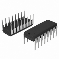
MC14556BCPG ON Semiconductor, MC14556BCPG Datasheet - Page 3

MC14556BCPG
Manufacturer Part Number
MC14556BCPG
Description
IC DCODER/DEMUX DUAL 1:4 16-DIP
Manufacturer
ON Semiconductor
Series
1400r
Type
Decoder/Demultiplexerr
Specifications of MC14556BCPG
Circuit
1 x 2:4
Independent Circuits
1
Voltage Supply Source
Dual Supply
Voltage - Supply
3 V ~ 18 V
Operating Temperature
-55°C ~ 125°C
Mounting Type
Through Hole
Package / Case
16-DIP (0.300", 7.62mm)
Product
Decoders, Encoders, Multiplexers & Demultiplexers
Logic Family
4000B
Supply Voltage (max)
18 V
Supply Voltage (min)
3 V
Maximum Operating Temperature
+ 125 C
Minimum Operating Temperature
- 55 C
Mounting Style
Through Hole
Circuit Type
Low-Power Schottky
Current, Supply
600 μA
Function Type
2-Channels
Logic Function
Decoder/Demultiplexer
Logic Type
CMOS
Number Of Circuits
Dual
Package Type
PDIP-16
Special Features
Binary
Temperature, Operating, Range
-55 to +125 °C
Voltage, Supply
3 to 18 VDC
No. Of Outputs
4
Supply Voltage Range
3V To 18V
Logic Case Style
DIP
No. Of Pins
16
Operating Temperature Range
-55°C To +125°C
Filter Terminals
DIP
Rohs Compliant
Yes
Family Type
4000 CMOS
Lead Free Status / RoHS Status
Lead free / RoHS Compliant
Current - Output High, Low
-
Lead Free Status / Rohs Status
Lead free / RoHS Compliant
Other names
MC14556BCPG
MC14556BCPGOS
MC14556BCPGOS
Î Î Î Î Î Î Î Î Î Î Î Î Î Î Î Î Î Î Î Î Î Î Î Î Î Î Î Î Î Î Î Î Î
Î Î Î Î Î Î Î Î Î Î Î Î Î Î Î Î Î Î Î Î Î Î Î Î Î Î Î Î Î Î Î Î Î
5. The formulas given are for the typical characteristics only at 25°C.
6. Data labelled “Typ” is not to be used for design purposes but is intended as an indication of the IC’s potential performance.
SWITCHING CHARACTERISTICS
Output Rise and Fall Time
Propagation Delay Time − A, B to Output
Propagation Delay Time − E to Output
Figure 1. Dynamic Power Dissipation Signal Waveforms
t
t
t
t
t
t
t
t
t
(50% DUTY CYCLE)
(50% DUTY CYCLE)
TLH
TLH
TLH
PLH
PLH
PLH
PLH
PLH
PLH
All 8 outputs connect to respective C
f in respect to a system clock.
OUTPUT Q1
, t
, t
, t
, t
, t
, t
, t
, t
, t
A INPUTS
B INPUTS
THL
THL
THL
PHL
PHL
PHL
PHL
PHL
PHL
= (1.5 ns/pF) C
= (0.75 ns/pF) C
= (0.55 ns/pF) C
= (1.7 ns/pF) C
= (0.66 ns/pF) C
= (0.5 ns/pF) C
= (1.7 ns/pF) C
= (0.66 ns/pF) C
= (0.5 ns/pF) C
20 ns
Characteristic
INPUT E LOW
A
B
E
*Eliminated for MC14555B
L
L
L
L
L
L
L
L
L
+ 25 ns
+ 135 ns
+ 45 ns
+ 115 ns
+ 40 ns
2f
1
+ 12.5 ns
+ 9.5 ns
+ 62 ns
+ 52 ns
(Note 5) (C
20 ns
L
loads.
10%
50%
90%
MC14555B, MC14556B
L
= 50 pF, T
http://onsemi.com
LOGIC DIAGRAM
Symbol
(1/2 of Dual)
t
t
t
t
t
t
TLH
PLH
PLH
A
THL
PHL
PHL
= 25°C)
V
V
V
V
V
V
DD
SS
DD
SS
OH
OL
,
,
,
3
V
5.0
5.0
5.0
10
15
10
15
10
15
DD
OUTPUT Q3
OUTPUT Q3
MC14556B
MC14555B
Figure 2. Dynamic Signal Waveforms
INPUT B
20 ns
Min
−
−
−
−
−
−
−
−
−
t
PHL
t
PLH
t
THL
*
*
*
*
t
TLH
INPUT A HIGH, INPUT E LOW
(Note 6)
90%
50%
10%
Q0
Q1
Q2
Q3
Typ
100
220
200
50
40
95
70
85
65
90%
50%
10%
90%
50%
10%
Max
200
100
440
190
140
400
170
130
80
20 ns
t
PLH
t
PHL
t
TLH
t
THL
Unit
V
V
V
V
V
V
ns
ns
ns
SS
DD
OH
OL
OH
OL


