MC74ACT02DR2G ON Semiconductor, MC74ACT02DR2G Datasheet - Page 9
MC74ACT02DR2G
Manufacturer Part Number
MC74ACT02DR2G
Description
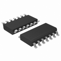
IC GATE NOR QUAD TTL 2INP 14SOIC
Manufacturer
ON Semiconductor
Series
74ACTr
Datasheet
1.MC74ACT02DG.pdf
(10 pages)
Specifications of MC74ACT02DR2G
Logic Type
NOR Gate
Number Of Inputs
2
Number Of Circuits
4
Current - Output High, Low
24mA, 24mA
Voltage - Supply
4.5 V ~ 5.5 V
Operating Temperature
-40°C ~ 85°C
Mounting Type
Surface Mount
Package / Case
14-SOIC (3.9mm Width), 14-SOL
Logic Family
ACT
Logical Function
NOR
Number Of Elements
4
High Level Output Current
-24mA
Low Level Output Current
24mA
Propagation Delay Time
10ns
Operating Supply Voltage (typ)
5V
Operating Temp Range
-40C to 85C
Package Type
SOIC
Number Of Outputs
1
Technology
CMOS
Mounting
Surface Mount
Pin Count
14
Operating Temperature Classification
Industrial
Quiescent Current
4uA
Operating Supply Voltage (max)
5.5V
Operating Supply Voltage (min)
4.5V
Lead Free Status / RoHS Status
Lead free / RoHS Compliant
Other names
MC74ACT02DR2GOS


−T−
0.15 (0.006) T
0.15 (0.006) T
0.10 (0.004)
SEATING
PLANE
L
U
U
PIN 1
IDENT.
2X
D
S
S
L/2
C
14
1
0.36
G
14X
14X
*For additional information on our Pb−Free strategy and soldering
−V−
A
details, please download the ON Semiconductor Soldering and
Mounting Techniques Reference Manual, SOLDERRM/D.
K
0.10 (0.004)
REF
8
7
SOLDERING FOOTPRINT*
M
−U−
PACKAGE DIMENSIONS
1
B
T
H
1.26
14X
U
http://onsemi.com
J J1
N
CASE 948G−01
S
N
TSSOP−14
DETAIL E
ISSUE B
V
7.06
S
DETAIL E
9
SECTION N−N
Ç Ç Ç
Ç Ç Ç
É É É
Ç Ç Ç
É É É
F
K1
K
0.25 (0.010)
M
DIMENSIONS: MILLIMETERS
−W−
NOTES:
0.65
PITCH
1. DIMENSIONING AND TOLERANCING PER
2. CONTROLLING DIMENSION: MILLIMETER.
3. DIMENSION A DOES NOT INCLUDE MOLD
4. DIMENSION B DOES NOT INCLUDE
5. DIMENSION K DOES NOT INCLUDE
6. TERMINAL NUMBERS ARE SHOWN FOR
7. DIMENSION A AND B ARE TO BE
ANSI Y14.5M, 1982.
FLASH, PROTRUSIONS OR GATE BURRS.
MOLD FLASH OR GATE BURRS SHALL NOT
EXCEED 0.15 (0.006) PER SIDE.
INTERLEAD FLASH OR PROTRUSION.
INTERLEAD FLASH OR PROTRUSION SHALL
NOT EXCEED 0.25 (0.010) PER SIDE.
DAMBAR PROTRUSION. ALLOWABLE
DAMBAR PROTRUSION SHALL BE 0.08
(0.003) TOTAL IN EXCESS OF THE K
DIMENSION AT MAXIMUM MATERIAL
CONDITION.
REFERENCE ONLY.
DETERMINED AT DATUM PLANE −W−.
DIM
K1
J1
A
B
C
D
G
H
K
M
F
J
L
MILLIMETERS
MIN
4.90
4.30
0.05
0.50
0.50
0.09
0.09
0.19
0.19
−−−
0
0.65 BSC
6.40 BSC
_
MAX
5.10
4.50
1.20
0.15
0.75
0.60
0.20
0.16
0.30
0.25
8
_
0.193
0.169
0.002
0.020
0.020
0.004
0.004
0.007
0.007
MIN
−−− 0.047
0.026 BSC
0.252 BSC
0
INCHES
_
0.200
0.177
0.006
0.030
0.024
0.008
0.006
0.012
0.010
MAX
8
_
Related parts for MC74ACT02DR2G
Image
Part Number
Description
Manufacturer
Datasheet
Request
R

Part Number:
Description:
ON Semiconductor [VOLTAGE REGULATOR]
Manufacturer:
ON Semiconductor
Datasheet:
Part Number:
Description:
357-036-542-201 CARDEDGE 36POS DL .156 BLK LOPRO
Manufacturer:
ON Semiconductor
Datasheet:
Part Number:
Description:
357-036-542-201 CARDEDGE 36POS DL .156 BLK LOPRO
Manufacturer:
ON Semiconductor
Datasheet:
Part Number:
Description:
357-036-542-201 CARDEDGE 36POS DL .156 BLK LOPRO
Manufacturer:
ON Semiconductor
Datasheet:
Part Number:
Description:
357-036-542-201 CARDEDGE 36POS DL .156 BLK LOPRO
Manufacturer:
ON Semiconductor
Datasheet:
Part Number:
Description:
357-036-542-201 CARDEDGE 36POS DL .156 BLK LOPRO
Manufacturer:
ON Semiconductor
Datasheet:
Part Number:
Description:
357-036-542-201 CARDEDGE 36POS DL .156 BLK LOPRO
Manufacturer:
ON Semiconductor
Datasheet:
Part Number:
Description:
357-036-542-201 CARDEDGE 36POS DL .156 BLK LOPRO
Manufacturer:
ON Semiconductor
Datasheet:
Part Number:
Description:
357-036-542-201 CARDEDGE 36POS DL .156 BLK LOPRO
Manufacturer:
ON Semiconductor
Datasheet:
Part Number:
Description:
357-036-542-201 CARDEDGE 36POS DL .156 BLK LOPRO
Manufacturer:
ON Semiconductor
Datasheet:
Part Number:
Description:
357-036-542-201 CARDEDGE 36POS DL .156 BLK LOPRO
Manufacturer:
ON Semiconductor
Datasheet:
Part Number:
Description:
Manufacturer:
ON Semiconductor
Datasheet:
Part Number:
Description:
Manufacturer:
ON Semiconductor
Datasheet:
Part Number:
Description:
Manufacturer:
ON Semiconductor
Datasheet: