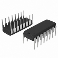
MC14518BCPG ON Semiconductor, MC14518BCPG Datasheet - Page 3

MC14518BCPG
Manufacturer Part Number
MC14518BCPG
Description
IC COUNTER BCD 8BIT 16DIP
Manufacturer
ON Semiconductor
Series
4000Br
Type
Decader
Specifications of MC14518BCPG
Logic Type
BCD Counter
Direction
Up
Number Of Elements
2
Number Of Bits Per Element
4
Reset
Asynchronous
Timing
Synchronous
Count Rate
8MHz
Trigger Type
Positive, Negative
Voltage - Supply
3 V ~ 18 V
Operating Temperature
-55°C ~ 125°C
Mounting Type
Through Hole
Package / Case
16-DIP (0.300", 7.62mm)
Counter Type
Binary
Counting Sequence
Up
Number Of Circuits
2
Logic Family
14518
Propagation Delay Time
560 ns, 230 ns, 160 ns
Supply Voltage (max)
18 V
Maximum Operating Temperature
+ 125 C
Minimum Operating Temperature
- 55 C
Function
Counter
Mounting Style
Through Hole
Operating Supply Voltage
3 V to 18 V
Circuit Type
Low-Power Schottky
Current, Supply
600 μA
Function Type
4-Stages
Logic Function
Counter
Package Type
PDIP-16
Temperature, Operating, Range
-55 to +125 °C
Voltage, Supply
3 to 18 VDC
Technology
CMOS
Number Of Elements
2
Number Of Bits
4
Logical Function
Counter
Operating Supply Voltage (typ)
3.3/5/9/12/15V
Output Type
Standard
Operating Temp Range
-55C to 125C
Operating Supply Voltage (min)
3V
Operating Supply Voltage (max)
18V
Operating Temperature Classification
Military
Mounting
Through Hole
Pin Count
16
Clock Frequency
8MHz
Count Maximum
9
Supply Voltage Range
3V To 18V
Logic Case Style
DIP
No. Of Pins
16
Operating Temperature Range
-55°C To +125°C
Filter Terminals
DIP
Rohs Compliant
Yes
Clock Frequency Max
4MHz
Lead Free Status / RoHS Status
Lead free / RoHS Compliant
Other names
MC14518BCPGOS
Available stocks
Company
Part Number
Manufacturer
Quantity
Price
Part Number:
MC14518BCPG
Manufacturer:
ON/安森美
Quantity:
20 000
Î Î Î Î Î Î Î Î Î Î Î Î Î Î Î Î Î Î Î Î Î Î Î Î Î Î Î Î Î Î Î Î Î
Î Î Î Î Î Î Î Î Î Î Î Î Î Î Î Î Î Î Î Î Î Î Î Î Î Î Î Î Î Î Î Î Î
6. The formulas given are for the typical characteristics only at 25_C.
7. Data labelled “Typ” is not to be used for design purposes but is intended as an indication of the IC’s potential performance.
SWITCHING CHARACTERISTICS
Output Rise and Fall Time
Propagation Delay Time
Clock Pulse Width
Clock Pulse Frequency
Clock or Enable Rise and Fall Time
Enable Pulse Width
Reset Pulse Width
Reset Removal Time
t
t
t
Clock to Q/Enable to Q
Reset to Q
TLH
TLH
TLH
t
t
t
t
t
t
PLH
PLH
PLH
PHL
PHL
PHL
, t
, t
, t
, t
, t
, t
THL
THL
THL
= (1.7 ns/pF) C
= (0.66 ns/pF) C
= (0.66 ns/pF) C
PHL
PHL
PHL
= (1.5 ns/pF) C
= (0.75 ns/pF) C
= (0.55 ns/pF) C
= (1.7 ns/pF) C
= (0.66 ns/pF) C
= (0.5 ns/pF) C
Characteristic
L
L
L
+ 265 ns
+ 117 ns
+ 95 ns
L
L
L
+ 25 ns
L
L
+ 12.5 ns
+ 9.5 ns
L
+ 215 ns
+ 75 ns
+ 97 ns
Figure 1. Power Dissipation Test Circuit and Waveform
GENERATOR
(6.)
20 ns
PULSE
(C
L
500 μF
= 50 pF, T
MC14518B, MC14520B
50%
VARIABLE
WIDTH
A
= 25_C)
t
THL
Symbol
R
t
t
C
E
t
WH(E)
WH(R)
t
t
t
t
t
t
t
90%
TLH
PLH
w(H)
THL
PHL
PHL
w(L)
rem
f
I
, t
D
cl
Q0
Q1
Q2
Q3
V
TLH
,
,
DD
4
V
SS
10%
20 ns
C
V
5.0
5.0
5.0
5.0
5.0
5.0
5.0
5.0
5.0
L
10
15
10
15
10
15
10
15
10
15
10
15
10
15
10
15
10
15
DD
0.01 μF
CERAMIC
V
SS
C
L
C
Min
L
200
100
440
200
140
280
120
– 5
70
90
15
20
—
—
—
—
—
—
—
—
—
—
—
—
—
—
—
C
L
All Types
Typ
– 45
– 15
100
280
330
130
100
220
100
125
115
2.5
6.0
8.0
– 5
50
40
80
90
50
35
70
55
40
—
—
—
(7.)
Max
200
100
560
230
160
650
230
170
1.5
3.0
4.0
80
—
—
—
15
—
—
—
—
—
—
—
—
—
5
4
MHz
Unit
ns
ns
ns
ns
μs
ns
ns
ns


