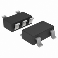
M74VHC1G125DTT1G ON Semiconductor, M74VHC1G125DTT1G Datasheet - Page 4

M74VHC1G125DTT1G
Manufacturer Part Number
M74VHC1G125DTT1G
Description
IC BUFFER TRI-ST NON-INV SOT235
Manufacturer
ON Semiconductor
Series
74VHCr
Datasheet
1.M74VHC1G125DFT2G.pdf
(6 pages)
Specifications of M74VHC1G125DTT1G
Logic Type
Buffer/Line Driver, Non-Inverting
Number Of Elements
1
Number Of Bits Per Element
1
Current - Output High, Low
8mA, 8mA
Voltage - Supply
2 V ~ 5.5 V
Operating Temperature
-55°C ~ 125°C
Mounting Type
Surface Mount
Package / Case
TSOT-23-5, TSOT-5, TSOP-5
Logic Family
74VHC
Number Of Channels Per Chip
Single
Polarity
Non-Inverting
Supply Voltage (max)
5.5 V
Supply Voltage (min)
2 V
Maximum Operating Temperature
125 C
Mounting Style
SMD/SMT
High Level Output Current
- 8 mA
Input Bias Current (max)
1 uA
Low Level Output Current
8 mA
Maximum Power Dissipation
200 mW
Minimum Operating Temperature
- 55 C
Number Of Lines (input / Output)
3
Output Type
3-State
Propagation Delay Time
11.5 ns @ 3.3 V or 7.5 ns @ 5 V
Current, Supply
40 μA
Function Type
1-Channel
Logic Function
Buffer
Number Of Circuits
Single
Package Type
TSOP-5/SOT23/SC-59
Special Features
Non-Inverting, Tri-State
Temperature, Operating, Range
-55 to +125 °C
Voltage, Supply
2 to 5.5 V
Logic Device Type
Buffer, Non Inverting
Supply Voltage Range
2V To 5.5V
Logic Case Style
SOT-23
No. Of Pins
5
Operating Temperature Range
-55°C To +125°C
Filter Terminals
SMD
Rohs Compliant
Yes
Family Type
VHC
Lead Free Status / RoHS Status
Lead free / RoHS Compliant
Other names
M74VHC1G125DTT1GOS
MC74VHC1G125DTT1G
MC74VHC1G125DTT1GOS
MC74VHC1G125DTT1GOS
MC74VHC1G125DTT1G
MC74VHC1G125DTT1GOS
MC74VHC1G125DTT1GOS
Available stocks
Company
Part Number
Manufacturer
Quantity
Price
Part Number:
M74VHC1G125DTT1G
Manufacturer:
ON/安森美
Quantity:
20 000
†For information on tape and reel specifications, including part orientation and tape sizes, please refer to our Tape and Reel Packaging
ORDERING INFORMATION
Specifications Brochure, BRD8011/D.
MC74VHC1G125DFT1
M74VHC1G125DFT1G
MC74VHC1G125DFT2
M74VHC1G125DFT2G
MC74VHC1G125DTT1
M74VHC1G125DTT1G
A
Y
*Includes all probe and jig capacitance
Figure 4. Switching Wave Forms
t
PLH
50% V
DEVICE
UNDER
Figure 6. Test Circuit
TEST
CC
50%
Device
OUTPUT
TEST POINT
INPUT
C
L
*
Figure 8. Input Equivalent Circuit
t
PHL
SWITCHING WAVEFORMS
GND
V
CC
MC74VHC1G125
http://onsemi.com
TSC−88A/SOT−353/SC−70
SC−88A/SOT−353/SC−70
SC−88A/SOT−353/SC−70
SC−88A/SOT−353/SC−70
TSOP−5/SOT−23/SC−59
TSOP−5/SOT−23/SC−59
4
(Pb−Free)
(Pb−Free)
(Pb−Free)
Package
DEVICE
UNDER
TEST
OE
Y
Y
*Includes all probe and jig capacitance
OUTPUT
TEST POINT
50%
Figure 7. Test Circuit
50% V
50% V
t
t
PZH
1 kW
PZL
Figure 5.
C
CC
L
CC
*
t
t
PHZ
PLZ
3000 Units / Tape & Reel
CONNECT TO V
TESTING t
CONNECT TO GND WHEN
TESTING t
Shipping
V
V
OL
OH
+ 0.3V
− 0.3V
PLZ
PHZ
V
GND
HIGH
IMPEDANCE
HIGH
IMPEDANCE
AND t
†
AND t
CC
CC
WHEN
PZL.
PZH.


