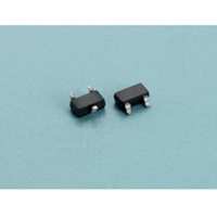
AP432 Advanced Power Electronics Corp., AP432 Datasheet - Page 4

AP432
Manufacturer Part Number
AP432
Description
Manufacturer
Advanced Power Electronics Corp.
Datasheet
1.AP432.pdf
(11 pages)
Specifications of AP432
Vref
1.24
Cathode Voltage
20
Continuous Cathode Current
250
Accuracy
0.5%, 1%
Minimum Cathode Current For Regulation Typ.
0.15
Package
SOP8,SOT89,TO92,SOT23,SOT23-5
Available stocks
Company
Part Number
Manufacturer
Quantity
Price
Company:
Part Number:
AP432
Manufacturer:
EVERLIGHT
Quantity:
5 000
Company:
Part Number:
AP432
Manufacturer:
EVELGH
Quantity:
2 000
Part Number:
AP432
Manufacturer:
台湾
Quantity:
20 000
Part Number:
AP4320AK6TR-G1
Manufacturer:
BCD
Quantity:
20 000
Part Number:
AP4320BK6TR-G1
Manufacturer:
DIODES/美台
Quantity:
20 000
Company:
Part Number:
AP432AR
Manufacturer:
ATC
Quantity:
10 000
Part Number:
AP432ARA
Manufacturer:
ATC
Quantity:
20 000
Part Number:
AP432ARL-7
Manufacturer:
DIODES/美台
Quantity:
20 000
Company:
Part Number:
AP432AV
Manufacturer:
ATC
Quantity:
10 000
Adjustable Precision Shunt Regulator
Note 3. Deviation of reference input voltage, V
The average temperature coefficient of the reference input voltage αV
Where:
T2 – T1 = full temperature change.
αV
Note 4. The dynamic output impedance, R
When the device is programmed with two external resistors R1 and R2 (see Figure 2.), the dynamic output
impedance of the overall circuit, is defined as:
Advanced Power Electronics Corp.
www.a-power.com.tw
REF
Test Circuits
Fig1. Test Circuit for V
the full temperature range.
can be positive or negative depending on whether the slope is positive or negative.
Advanced Power
Electronics Corp.
V
REF
Input
I
KA
KA
= V
V
V
V
KA
REF
MAX
MIN
α
V
REF
T
V
I
KA
Fig2. Test circuit for V
=
=
Z
Z
, is defined as:
KA
R1
R2
(
V
V
'
REF
REF
DEV
=
V
Z
DEV
∆
TEMPERATURE
(1
T
∆
, is defined as the maximum variation of the reference over
KA
(25
I
V
v
V
2
REF
i
DEV
REF
+
≈
−
°
C)
=
R2
R1
T
Z
= V
)
1
∆
KA
IN
∆
×
V
)
MAX
I
10
KA
+
KA
V
KA
(
I
I
6
1
KA
- V
REF
KA
>V
+
MIN
……………………..……………….. (
R2
R1
⋅
REF
R1
)
REF
Fig3. Test Circuit for off-state Current
is defined as:
T
2
IN
V
KA
I
Z(OFF)
AP432
ppm
°
C
4
)


