AP1005BSQ Advanced Power Electronics Corp., AP1005BSQ Datasheet

The AP1005BSQ used the latest APEC Power MOSFET silicon technology with the advanced technology packaging to provide the lowest on-resistance loss, low profile and dual sided cooling compatible

AP1005BSQ

Manufacturer Part Number
AP1005BSQ
Description
The AP1005BSQ used the latest APEC Power MOSFET silicon technology with the advanced technology packaging to provide the lowest on-resistance loss, low profile and dual sided cooling compatible
Manufacturer
Advanced Power Electronics Corp.
Datasheet

Specifications of AP1005BSQ

Vds
30V
Vgs
±20V
Rds(on) / Max(m?) Vgs@10v
3.8
Rds(on) / Max(m?) Vgs@4.5v
7.5
Qg (nc)
16.6
Qgs (nc)
3
Qgd (nc)
9.2
Id(a)
19
Pd(w)
2.2
Configuration
Single N
Package
GreenFET-SQ
▼ Lead-Free Package
▼ Low Conductance Loss
▼ Low Profile ( < 0.7mm )
▼ Compatible with DirectFET® Package SQ
V
V
I
I
I
I
P
P
P
E
I
T
T
Rthj-c
Rthj-a
Data and specifications subject to change without notice
Description
Absolute Maximum Ratings
Thermal Data
(A) GreenFET
registered trademark of International Rectifier Corporation.
D
D
D
DM
AR
The AP1005BSQ used the latest APEC Power MOSFET silicon technology
with the advanced technology packaging to provide the lowest on-resistance
loss, low profile and dual sided cooling compatible.
The GreenFET
and is ideal for power application, especially for high frequency / high
efficiency DC-DC converters.
STG
J
DS
GS
D
D
D
AS
@T
@T
@T
@T
@T
@T
Footprint and Outline
A
A
C
Symbol
A
A
C
=25℃
=70℃
=25℃
=25℃
=70℃
=25℃
TM
Advanced Power
Electronics Corp.
products use DirectFET ® technology licensed from International Rectifier Corporation. DirectFET ® is a
TM(A)
Drain-Source Voltage
Gate-Source Voltage
Continuous Drain Current, V
Pulsed Drain Current
Total Power Dissipation
Single Pulse Avalanche Energy
Avalanche Current
Storage Temperature Range
Operating Junction Temperature Range
Maximum Thermal Resistance, Junction-case
Maximum Thermal Resistance, Junction-ambient
package is compatible with existing soldering techniques
Parameter
1
3
3
4
GS
GS
GS
@ 10V
@ 10V
@ 10V
5
G
3
3
4
N-CHANNEL ENHANCEMENT MODE
POWER MOSFET
4
3
D
S
Halogen-Free Product
-40 to 150
-40 to 150
Rating
BV
R
I
D
41.7
28.8
+20
150
2.2
1.4
30
19
15
84
24
DS(ON)
DSS
58
3
AP1005BSQ
D
GreenFET
G
SQ
3.8mΩ
201112234
Units
℃/W
℃/W
30V
19A
S
W
W
W
mJ
TM
V
V
A
A
A
A
A
D
1

Related parts for AP1005BSQ

AP1005BSQ Summary of contents

Page 1

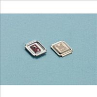
... Low Profile ( < 0.7mm ) ▼ Compatible with DirectFET® Package SQ Footprint and Outline Description The AP1005BSQ used the latest APEC Power MOSFET silicon technology with the advanced technology packaging to provide the lowest on-resistance loss, low profile and dual sided cooling compatible. TM(A) ...

Page 2

... AP1005BSQ Electrical Characteristics@T Symbol Parameter BV Drain-Source Breakdown Voltage DSS R Static Drain-Source On-Resistance DS(ON) V Gate Threshold Voltage GS(th) g Forward Transconductance fs I Drain-Source Leakage Current DSS Drain-Source Leakage Current (T I Gate-Source Leakage GSS 2 Q Total Gate Charge g Q Pre-V Gate-Source Charge gs1 th Q Post-V Gate-Source Charge ...

Page 3

... Fig 2. Typical Output Characteristics 2 I =19A D V =10V G 1.6 1.2 0.8 0 -50 Fig 4. Normalized On-Resistance v.s. Junction Temperature 1.6 1 0.8 0.4 0 1.5 -50 Fig 6. Gate Threshold Voltage v.s. Junction Temperature AP1005BSQ o T =150 C 10V A 7.0V 6.0V 5.0V V =4. Drain-to-Source Voltage ( 100 150 Junction Temperature ( ...

Page 4

... AP1005BSQ 10 I =15A D V =13V Total Gate Charge (nC) G Fig 7. Gate Charge Characteristics 1000 100 Operation in this area limited by R DS(ON =25 C 0.1 A Single Pulse 0.01 0.01 0 Drain-to-Source Voltage (V) DS Fig 9. Maximum Safe Operating Area V DS ...

Related keywords