AD8324ACP Analog Devices Inc, AD8324ACP Datasheet - Page 12
AD8324ACP
Manufacturer Part Number
AD8324ACP
Description
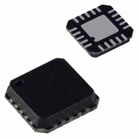
IC LINE DRIVER CATV 3.3V 20LFCSP
Manufacturer
Analog Devices Inc
Type
Line Driver, Transmitterr
Datasheet
1.AD8324ACPZ.pdf
(16 pages)
Specifications of AD8324ACP
Applications
Modems, CATV
Mounting Type
Surface Mount
Package / Case
20-LFCSP
Lead Free Status / RoHS Status
Lead free / RoHS Compliant
Available stocks
Company
Part Number
Manufacturer
Quantity
Price
Company:

Part Number:
AD8324ACPZ
Manufacturer:
MSTAR
Quantity:
2 356
Part Number:
AD8324ACPZ
Manufacturer:
ADI/亚德诺
Quantity:
20 000
Part Number:
AD8324ACPZ-REEL
Manufacturer:
ADI/亚德诺
Quantity:
20 000
Company:
Part Number:
AD8324ACPZ-REEL7
Manufacturer:
PWRI
Quantity:
2 582


AD8324
The BYP pin is used to decouple the output stage to ground.
Typically, for normal DOCSIS operation, the BYP pin should be
decoupled to ground with a 0.1 μF capacitor. However, in
applications that may require transient on/off times faster than
2 μs, smaller capacitors may be used, but it should be noted that
the BYP pin should always be decoupled to ground.
POWER SAVING FEATURES
The AD8324 incorporates three distinct methods of reducing
power consumption: transmit disable and sleep modes for
between-burst and shutdown modes, as well as gain dependent
quiescent current for transmit enable mode.
The asynchronous TXEN pin is used to place the AD8324 into
between-burst mode. In this reduced current state, the 75 Ω
output impedance is maintained. Applying Logic 0 to the TXEN
pin deactivates the on-chip amplifier, providing a 98.8% reduc-
tion in consumed power. For 3.3 V operation, the supply
current is typically reduced from 207 mA to 2.5 mA. In this
mode of operation, between-burst noise is minimized and high
input to output isolation is achieved. In addition to the TXEN
pin, the AD8324 also incorporates an asynchronous SLEEP pin,
which may be used to further reduce the supply current to
approximately 30 μA. Applying Logic 0 to the SLEEP pin places
the amplifier into SLEEP mode. Transitioning into or out of
SLEEP mode may result in a transient voltage at the output of
the amplifier.
In addition to the sleep and transmit disable functions, the
AD8324 provides yet another means of reducing system power
consumption. While in the transmit enable state, the AD8324
incorporates supply current scaling, which allows for lower
power consumption at lower gain codes. Figure 20 shows the
typical relationship between supply current and gain code.
DISTORTION, ADJACENT CHANNEL POWER, AND
DOCSIS
To deliver the DOCSIS required 58 dBmV of QPSK signal and
55 dBmV of 16 QAM signal, the PA is required to deliver up to
61 dBmV. This added power is required to compensate for
losses associated with the diplex filter or other passive compo-
nents that may be included in the upstream path of cable
modems or set-top boxes. It should be noted that the AD8324
was characterized with a differential input signal. Figures 7 to
10 show the AD8324 second and third harmonic distortion
performance versus the fundamental frequency for various
output power levels. These figures are useful for determining
the in-band harmonic levels from 5 MHz to 65 MHz.
Harmonics higher in frequency (above 42 MHz for DOCSIS
and above 65 MHz for Euro-DOCSIS) will be sharply
attenuated by the low-pass filter function of the diplexer.
Rev. A | Page 12 of 16
Another measure of signal integrity is adjacent channel power,
commonly referred to as ACP. DOCSIS 2.0, section 6.2.21.1.1
states, “Spurious emissions from a transmitted carrier may
occur in an adjacent channel that could be occupied by a carrier
of the same or different symbol rates. ” Figure 13 shows the
typical ACP for a 61 dBmV (approximately 12 dBm) QPSK
signal taken at the output of the AD8324 evaluation board. The
transmit channel width and adjacent channel width in Figure 13
correspond to the symbol rates of 160 kSym/s. Table 7 shows
the ACP results for the AD8324 driving a QPSK, 61 dBmV
signal for all conditions in DOCSIS Table 6-9, Adjacent
Channel Spurious Emissions.
UTILIZING DIPLEX FILTERS
The AD8324 was designed to drive 61 dBmV without any
external filtering and still meet DOCSIS spurious emissions and
distortion requirements. However, in most upstream CATV
applications, a diplex filter is used to separate the upstream and
downstream signal paths from one another. The diplex filter
does have insertion loss that the upstream driver needs to over-
come, but it also provides a low-pass filter. The addition of this
low-pass filter to the signal chain can greatly attenuate second
harmonic products of channels above 21 MHz and third
harmonic products of channels at or above 14 MHz up for
diplexers with a 42 MHz upstream cutoff. Similar performance
gains can be achieved using European-specified diplexers to
filter second harmonics for channels above 33 MHz and third
harmonics for channels above 22 MHz (65 MHz upstream
cutoff). This filtering allows the AD8324 to drive up to
63 dBmV of QPSK (this level can vary by application and
modulation type).
NOISE AND DOCSIS
At minimum gain, the AD8324 output noise spectral density is
1.3 nV/√Hz measured at 10 MHz. DOCSIS Table 6-10,
Spurious Emissions in 5 MHz to 42 MHz, specifies the output
noise for various symbol rates. The calculated noise power in
dBmV for 160 kSym/s is
Comparing the computed noise power of –65.7 dBmV to the
+8 dBmV signal yields –73.7 dBc, which meets the required
level set forth in DOCSIS Table 6-10. As the AD8324 gain is
increased above this minimum value, the output signal
increases at a faster rate than the noise, resulting in a signal-to-
noise ratio that improves with gain. In transmit disable mode,
the output noise spectral density is 1.1 nV/√Hz, which results in
–67 dBmV when computed over 160 kSym/s. The noise power
was measured directly at the AD8324AR-EVAL’s output.
20 × log [√(1.3 nV/√Hz)
2
× 160 kHz] + 60 = –65.7 dBmV
Related parts for AD8324ACP
Image
Part Number
Description
Manufacturer
Datasheet
Request
R

Part Number:
Description:
±1.7g Dual-Axis IMEMS Accelerometer Evaluation Board
Manufacturer:
Analog Devices Inc
Datasheet:

Part Number:
Description:
Inertial Sensor Evaluation System
Manufacturer:
Analog Devices Inc
Datasheet:
Part Number:
Description:
Manufacturer:
Analog Devices Inc
Datasheet:
Part Number:
Description:
Manufacturer:
Analog Devices Inc
Datasheet:
Part Number:
Description:
Manufacturer:
Analog Devices Inc
Datasheet:
Part Number:
Description:
Manufacturer:
Analog Devices Inc
Datasheet:
Part Number:
Description:
Manufacturer:
Analog Devices Inc
Datasheet:
Part Number:
Description:
Manufacturer:
Analog Devices Inc
Datasheet:
Part Number:
Description:
Manufacturer:
Analog Devices Inc
Datasheet:
Part Number:
Description:
Manufacturer:
Analog Devices Inc
Datasheet:
Part Number:
Description:
Manufacturer:
Analog Devices Inc
Datasheet:
Part Number:
Description:
Manufacturer:
Analog Devices Inc
Datasheet:
Part Number:
Description:
Manufacturer:
Analog Devices Inc
Datasheet: